
Carburetor

a carburetor and carbide technology, applied in the field of carburetor, can solve problems such as difficult installation, achieve the effects of reducing the flow cross-section, reducing the quantity of fuel supplied, and not making further processing steps difficult or prevented

Active Publication Date: 2009-02-24
ANDREAS STIHL AG & CO KG
View PDF12 Cites 18 Cited by
  • Summary
  • Abstract
  • Description
  • Claims
  • Application Information

AI Technical Summary

Benefits of technology

The present invention is a carburetor for an internal combustion engine that includes a partition section in the intake channel. The partition section is formed on the carburetor body and separates the intake channel into a mixture channel and a feed channel. The partition section has a flow guiding element that prevents fuel from passing into the feed channel and reduces resistance to flow. The technical effect of the invention is to improve the performance and efficiency of the carburetor by optimizing the flow of air and fuel in the intake channel.

Problems solved by technology

An insertion of a partition section into a region between a butterfly valve and a choke valve therefore requires a prescribed manufacturing sequence, thus making installation difficult.

Method used


Image

  • Carburetor
  • Carburetor
  • Carburetor

Examples


Embodiment Construction

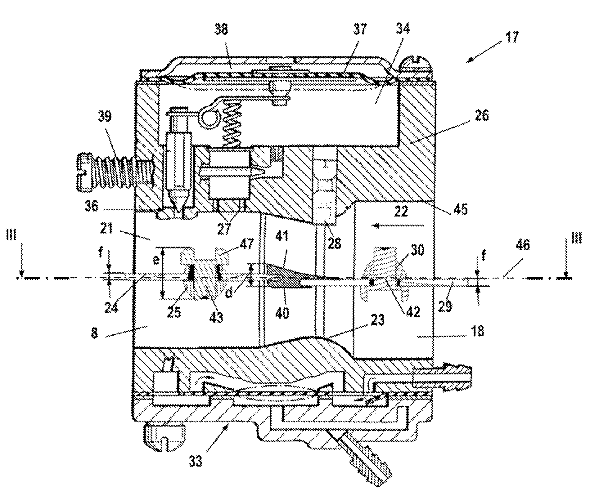
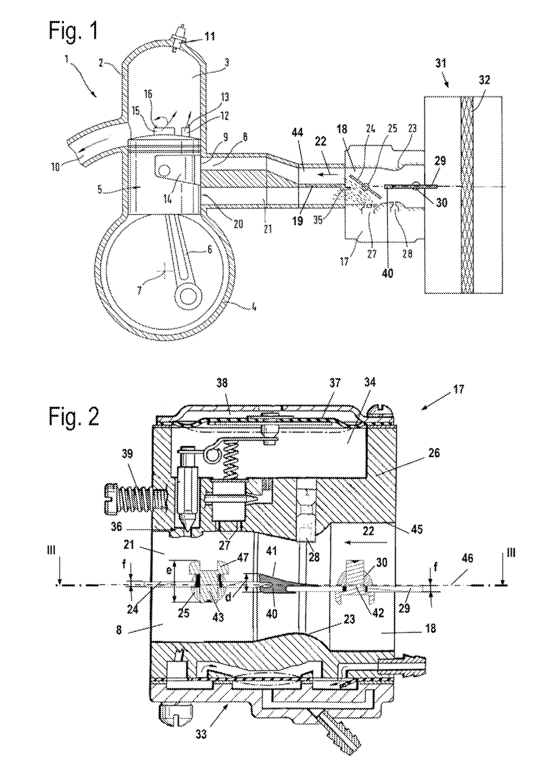
[0017]Referring now to the drawings in detail, FIG. 1 schematically shows an internal combustion engine, namely a two-cycle engine 1. The two-cycle engine 1 is embodied as a single-cylinder, two-cycle engine, and serves in particular for driving the tool of a manually guided implement, such as a cut-off machine, a power saw, a brushcutter, a trimmer, or the like. The two-cycle engine 1 has a cylinder 2, in which is formed a combustion chamber 3. The combustion chamber 3 is delimited by a piston 5 that is reciprocally mounted in the cylinder 2. By means of a connecting rod 6, the piston 5 drives a crankshaft 7 that is rotatably mounted in a crankcase 4.

[0018]The two-cycle engine 1 has an intake channel 44 that is connected to an air filter 31 via a carburetor 17. Disposed in the air filter 31 is filter material 32 that filters the combustion air that is drawn into the intake channel 44. Downstream of the carburetor 17, the intake channel 44 is divided by a partition 19 into a mixture...


PUM

PropertyMeasurementUnit
widthaaaaaaaaaa
distanceaaaaaaaaaa
pressureaaaaaaaaaa

Abstract

A carburetor having a carburetor body in which an intake channel portion is formed. At least one fuel opening opens out into the intake channel portion. Pivotably mounted in the intake channel portion is a butterfly valve that in a completely opened position divides the intake channel, in the region of the butterfly valve, into a mixture channel and a feed channel, so that in the completely opened position of the butterfly valve, flowing into the feed channel is combustion air having a fuel content that is less than the fuel content in the mixture channel. Provided in the intake channel portion is at least one partition section that extends between the feed channel and the mixture channel. The partition section is formed on the carburetor body.

Description

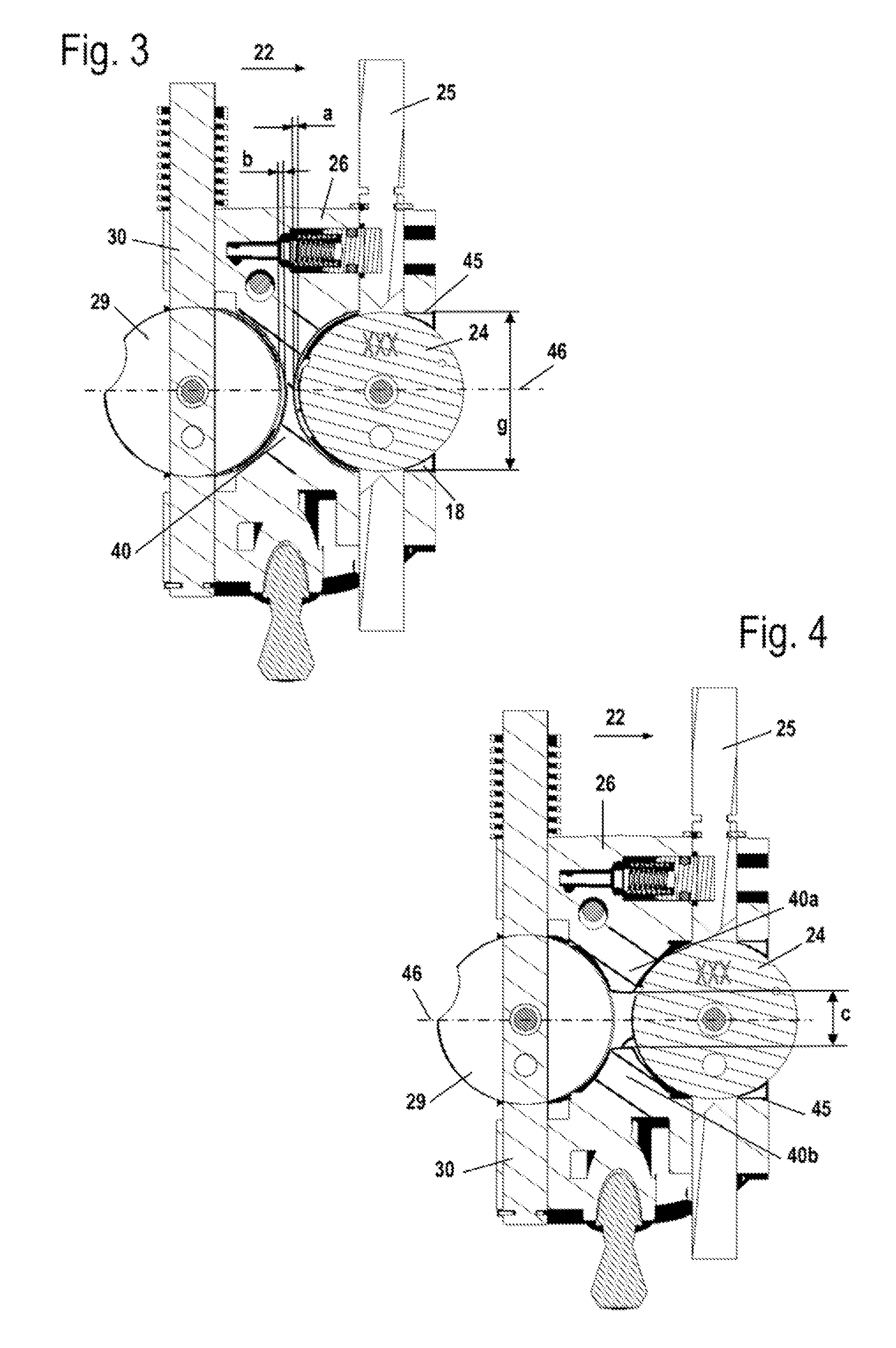
[0001]The instant application should be granted the priority date of Jul. 13, 2006 the filing date of the corresponding German patent application 10 2006 032 475.7.BACKGROUND OF THE INVENTION[0002]The present invention relates to a carburetor.[0003]U.S. 2005 / 0073062 A1 discloses a carburetor that has a butterfly valve. In order in the fully opened position of the butterfly valve to divide the intake channel into a mixture channel and an air channel, a partition section is inserted into the intake channel.[0004]It is an object of the present invention to provide a carburetor of the aforementioned general type that can be manufactured in a straightforward manner.BRIEF DESCRIPTION OF THE DRAWINGS[0005]This object, and other objects and advantages of the present invention, will appear more clearly from the following specification in conjunction with the accompanying schematic drawings, in which:[0006]FIG. 1 illustrates a two-cycle engine having a carburetor;[0007]FIG. 2 is an enlarged, ...

Claims


Application Information

Patent Timeline
Patent Type & Authority Patents(United States)
IPC IPC(8): F02M7/24
CPCF02B25/14F02B25/22F02M17/04F02B63/02F02B2075/025Y10S261/01
Inventor EBERHARDT, MAXIMILIANSCHIAUCH, PATRICK
Owner ANDREAS STIHL AG & CO KG
Learn More