Container cartridge for beverage dispenser and support structure thereof
a beverage dispenser and container technology, applied in the direction of pliable tubular containers, packaging goods types, liquid handling, etc., can solve the problems of cartridges that cannot be efficiently transported for recycling or disposal, remain bulky after use, etc., and achieve the effect of preventing deformation of the container cartridge during us
- Summary
- Abstract
- Description
- Claims
- Application Information
AI Technical Summary
Benefits of technology
Problems solved by technology
Method used
Image
Examples
first embodiment
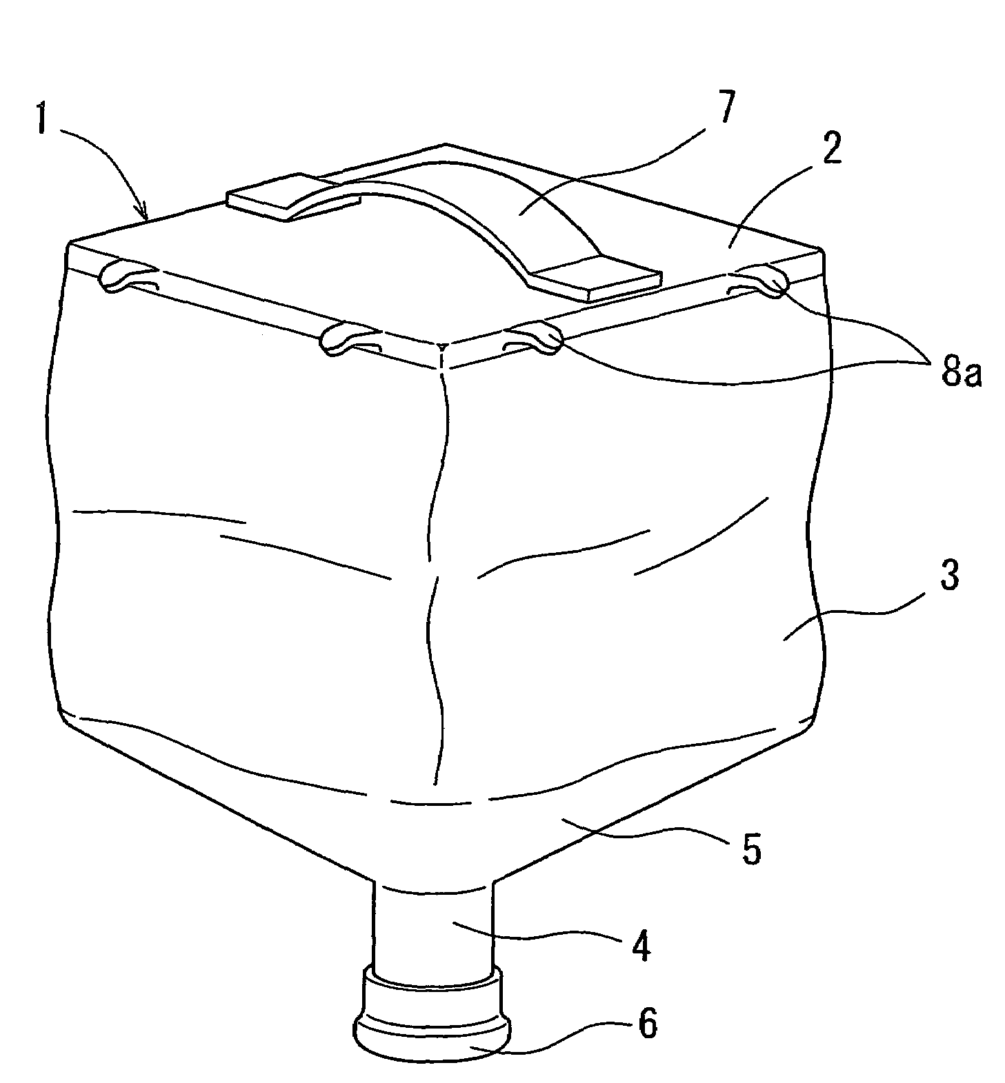
[0034]FIG. 6 shows a modification of the container cartridge 1 of the first embodiment, in which the flange 8 is replaced with a plurality of claws 8a protruding outwardly from the edge of the bottom wall 2. Like the flange 8, the claws 8a are adapted to engage the top end of the support structure 15.
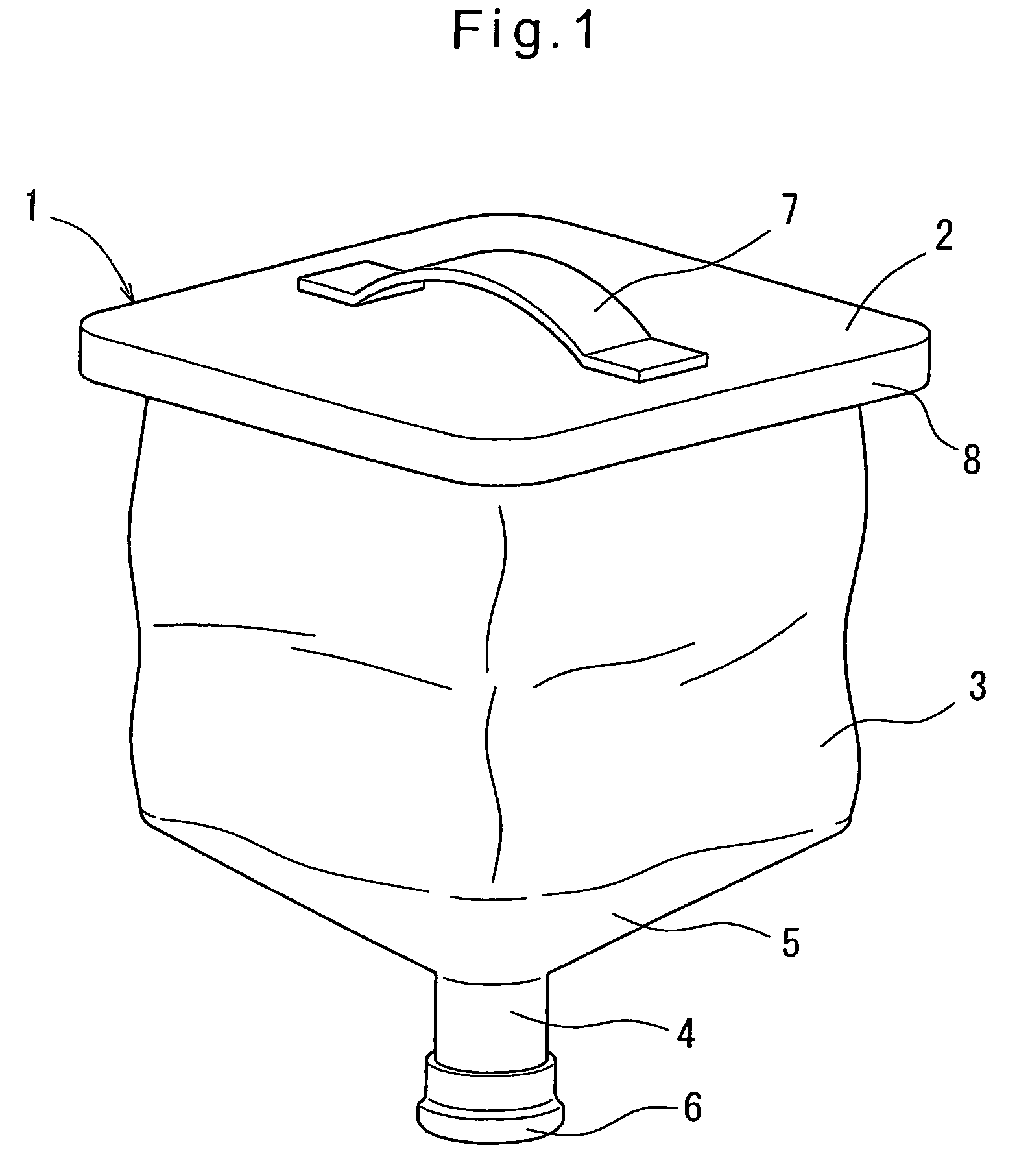
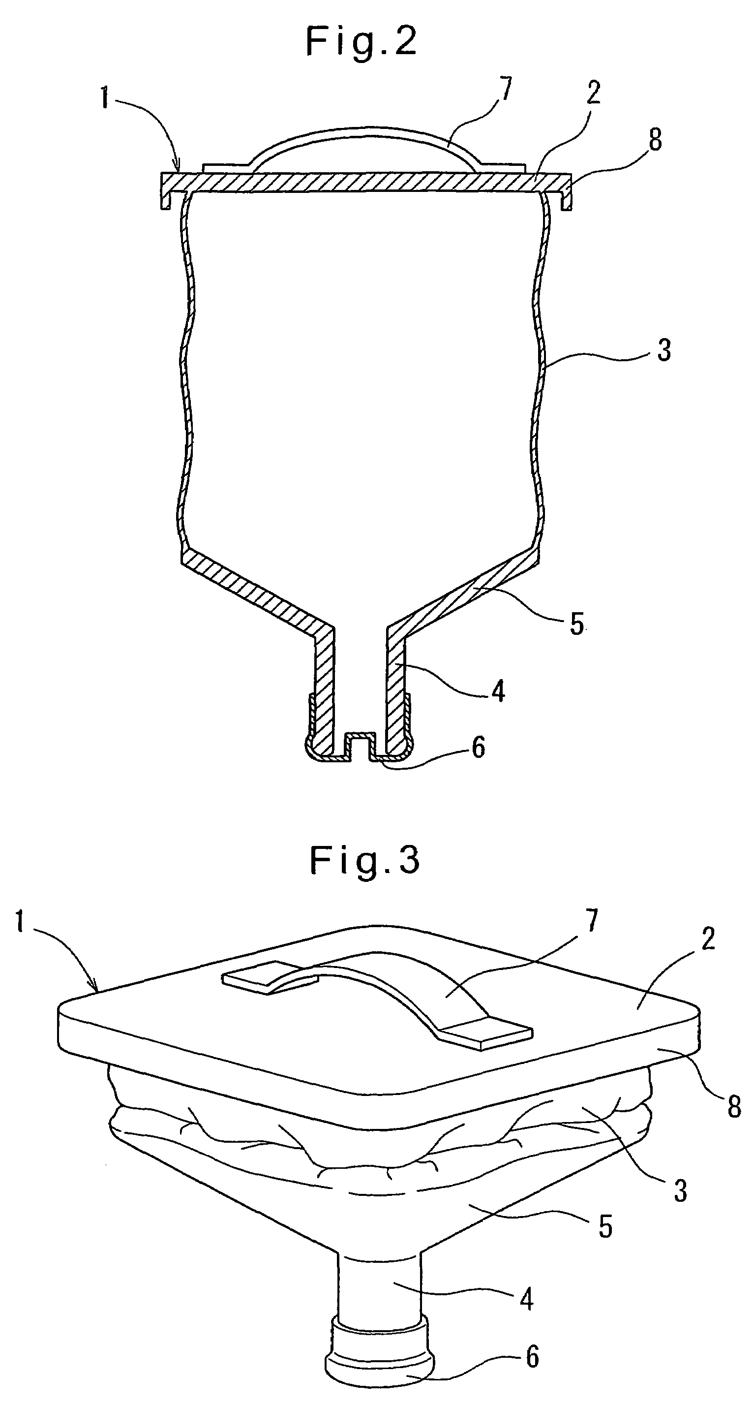
[0035]FIGS. 7A to 11 show the second embodiment. As shown in FIGS. 7A and 7B, the container cartridge 1 of the second embodiment is basically of the same structure as the container cartridge 1 of the first embodiment, and differs therefrom only in that the bottom wall 2 is thin, and in that a flange 9 is provided around the spout 4.
[0036]As shown in FIG. 8, beverage is poured into the container cartridge 1 through a hose 20 with the flange 9 supported on a bifurcated engaging member 21b secured to a rod 21a of a support 21 such that the container cartridge 1 is hung from the bifurcated member 21b. With this arrangement, the spout 4 is stably fixed in position so as to be always located ...
second embodiment
[0039]FIG. 10 shows a modification of the second embodiment, in which instead of the flange 9, a groove 9a is formed around the spout 4. The groove 9a is defined by an upper wall perpendicular to the spout 4 and a radially outwardly inclined lower wall. In this arrangement, beverage is poured into the container cartridge 1 through a hose 20 with the bifurcated engaging member 21b of the support 21 inserted in the groove 9a from both sides of the spout 5 such that the container cartridge 1 is hung from the bifurcated member 21b. With this arrangement, too, the spout 4 is stably fixed in position so as to be always located right under the outlet port of the hose 20.
[0040]The container cartridge of either embodiment is a bottle having a square cross-section, and made of a polyethylene. But the cartridge according to the present invention is not limited to such a shape. For example, it may be a bottle having a round cross-section. Also, it may be made of a material other than a polyethy...
PUM
| Property | Measurement | Unit |
|---|---|---|
| flexible | aaaaa | aaaaa |
| rigidity | aaaaa | aaaaa |
| flexibility | aaaaa | aaaaa |
Abstract
Description
Claims
Application Information
 - R&D
- Intellectual Property
- Life Sciences
- Materials
- Tech Scout
- Unparalleled Data Quality
- Higher Quality Content
- 60% Fewer Hallucinations
Browse by: Latest US Patents, China's latest patents, Technical Efficacy Thesaurus, Application Domain, Technology Topic, Popular Technical Reports.
© 2025 PatSnap. All rights reserved.Legal|Privacy policy|Modern Slavery Act Transparency Statement|Sitemap|About US| Contact US: help@patsnap.com


