
Scanning focal point apparatus

a focal point and scanning technology, applied in the field of collimators, can solve the problems of low spatial resolution, limited application range, and even further complicated situation, and achieve the effects of reducing cost, reducing space occupation, and reducing the number of collimator holes

Active Publication Date: 2009-02-17
NEUROLOGICA CORP
View PDF9 Cites 6 Cited by
  • Summary
  • Abstract
  • Description
  • Claims
  • Application Information

AI Technical Summary

Benefits of technology

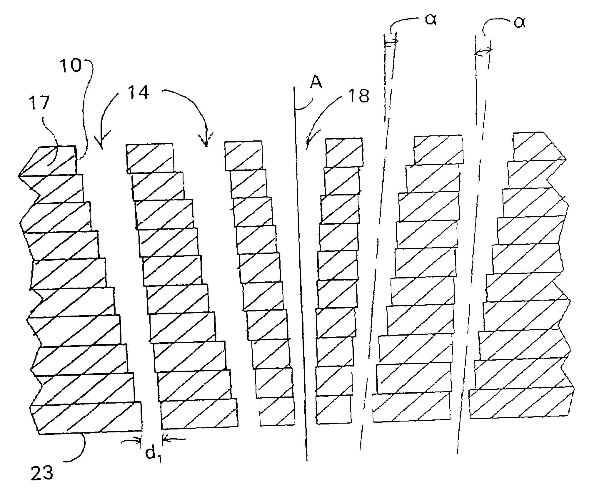
"The present invention provides a small collimator for SPECT machines that can accommodate small animals while maintaining high spatial resolution and sensitivity. The collimator is made up of a plurality of chemically etched plates with the same array of holes. By stacking the plates, the collimator achieves the same field of view and point-source resolution as a full-size collimator, but at a reduced size. The reduced size collimator is easy to manufacture and can be appropriately scaled to the size of the small animal. The invention also includes a reduced number of detectors and a simplified and cost-effective design."

Problems solved by technology

While SPECT is playing an important role in functional brain imaging, it has been limited in many applications by its low spatial resolution.
This situation is even further complicated where brain imaging is performed on a small animal such as a rat or mouse.
The brain structures of such animals are much smaller than a human brain structure and, therefore, the resolution of conventional SPECT scanners is grossly inadequate.
This is good for geometrical, spatial resolution, i.e., better for determining where the emitted gamma ray came from, but bad for sensitivity.
It is bad for sensitivity because the longer and narrower the hole(s) the fewer gamma rays will pass through the hole to impact on the scintillation crystal.
However, manufacturing a collimator small enough for adequate precision in both geometrical resolution and sensitivity for small animals is very difficult, inefficient and expensive using machined or cast lead blocks.

Method used


Image

  • Scanning focal point apparatus
  • Scanning focal point apparatus
  • Scanning focal point apparatus

Examples


Embodiment Construction

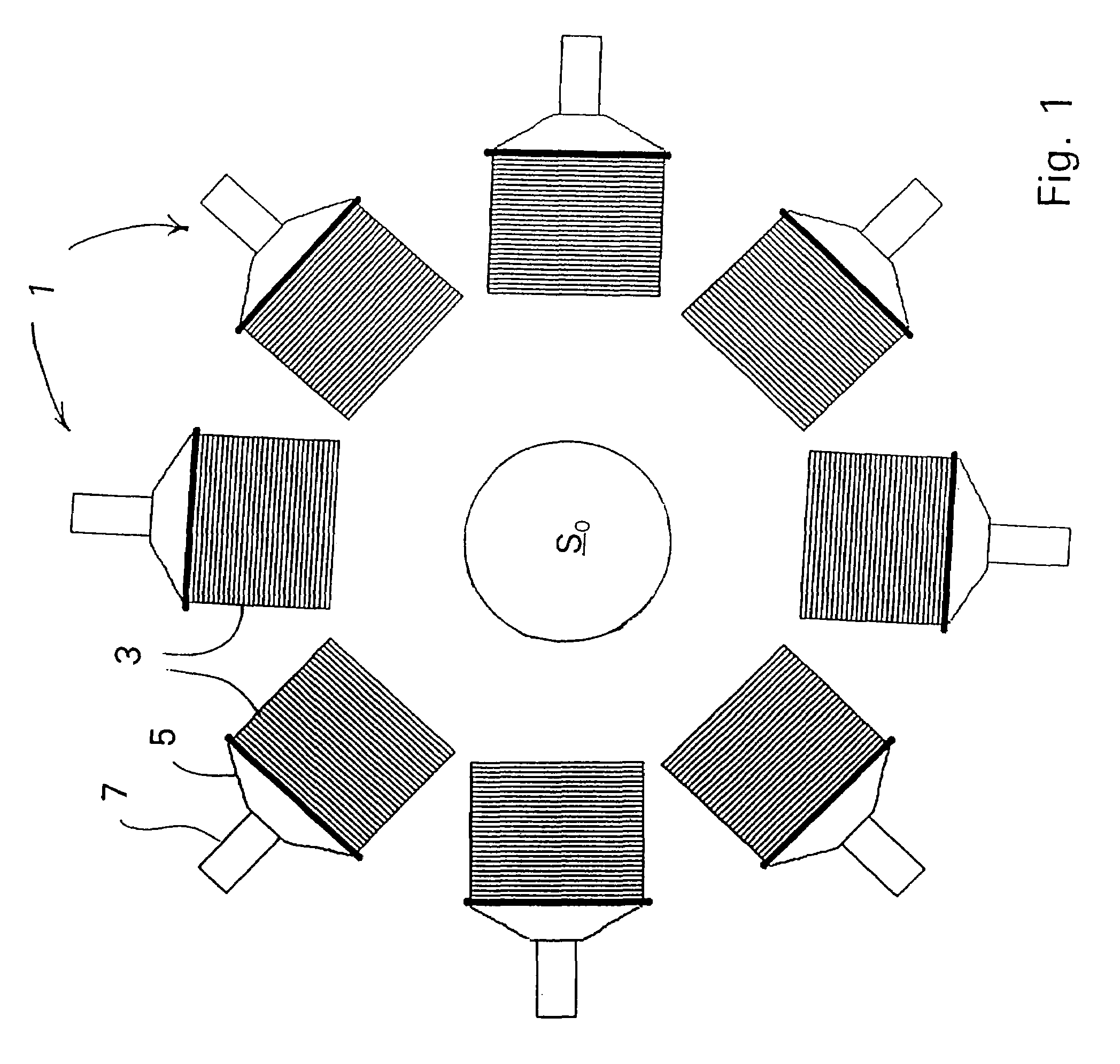
[0049]Observing FIG. 1, the present invention involves a scanning device akin to a scanning microscope. It uses eight identical scanning elements 1, each consisting of a three-dimensional (3D) point focused collimators 3 mated to one or more scintillating crystals 5 each associated with a photomultiplier tube 7. An acquisition or “scan ” of a source SOis nothing more than the 3D convolution described above of the source distribution of injected radionuclide with each detector's point-spread function (PSE). Although the present invention employs an iterative reconstruction to deal with absorption, scattering and other complications, a simple multi-detector, windowed, 3D deconvolution works quite well. As with any scanning system, intrinsic resolution and sensitivity are completely characterized by the point-spread functions of the detectors.

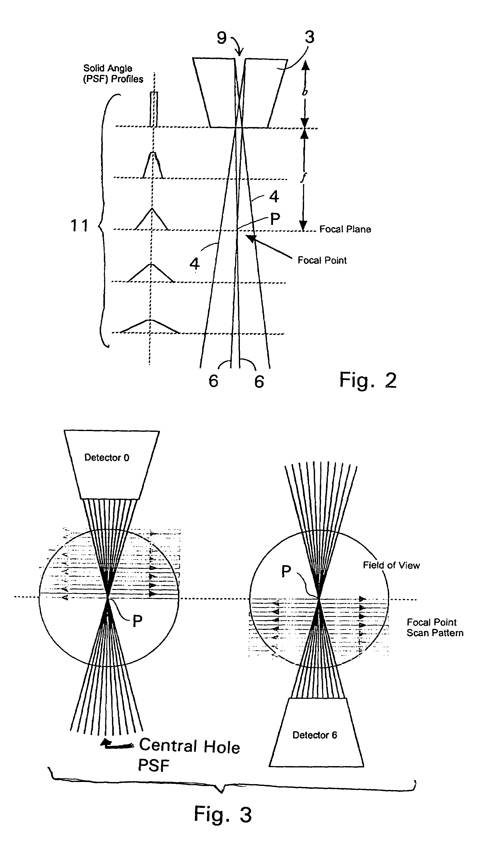
[0050]Turning to FIG. 2, to derive the PSF, first consider a detector whose collimator 3 consists of a single tapered hole 9 of bore length b and...


PUM


Abstract

A collimator, and in particular a method for making a collimator for use with a small high resolution single-photon emission computed tomographic (SPECT) imaging tool for small animal research. The collimator is sized, both functionally and structurally, particularly smaller than known collimators and appropriately scaled to achieve a highly sensitive collimator which facilitates desired reconstruction resolutions for small animals, as well as compliments other functional imaging modalities such as positron emission tomography (PET), functional magnetic resonance imaging (fMRI), electroencephalography (EEG), and event-related potential (ERP), magneto-encephalography (MEG), and near-infrared optical imaging.

Description

FIELD OF THE INVENTION[0001]The present invention relates to a collimator, and in particular a method for making a collimator for use with a small, high resolution single-photon emission computed tomographic (SPECT) imaging tool for small animal research. More particularly, the collimator is sized, both functionally and structurally, particularly smaller than known collimators and appropriately scaled to achieve a highly sensitive collimator which facilitates desired reconstruction resolutions for small animals, as well as compliments other functional imaging modalities such as positron emission tomography (PET), functional magnetic resonance imaging (fMRI), electroencephalography (EEG), and event-related potential (ERP), magneto-encephalography (MEG), and near-infrared optical imaging.BACKGROUND OF THE INVENTION[0002]In the last quarter century, the use of brain imaging for the treatment and understanding of diseases and genetic flaws has grown dramatically following the introducti...

Claims


Application Information

Patent Timeline
Patent Type & Authority Patents(United States)
IPC IPC(8): G21K1/02
CPCG01T1/1648
Inventor OLDEN, TIMOTHY HANSONMARTIN, DALE JOHNSEFRANEK, THOMAS CHRISTOPHER JOHNLAPOINT, GORDON ALLANSTODDART, HUGH ADAMSTODDART, HUGH FRANKLIN
Owner NEUROLOGICA CORP
Learn More