
Desulfurization in turbulent fluid bed reactor

a technology of turbulent fluid bed and desulfurization, which is applied in the direction of furnace types, lighting and heating apparatus, furnaces, etc., can solve the problems of large hydrogen consumption cost, high sulfur content of such automotive fuels, and reduced octane number, so as to reduce octane loss and hydrogen consumption, enhance the contact of hydrocarbon-containing fluid, and enhance desulfurization of hydrocarbon-containing fluid.

Active Publication Date: 2009-02-17
CHINA PETROCHEMICAL CORP
View PDF10 Cites 41 Cited by
  • Summary
  • Abstract
  • Description
  • Claims
  • Application Information

AI Technical Summary

Benefits of technology

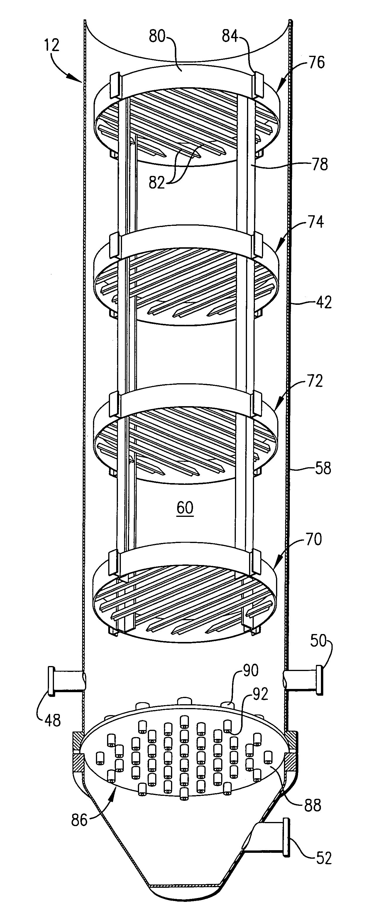
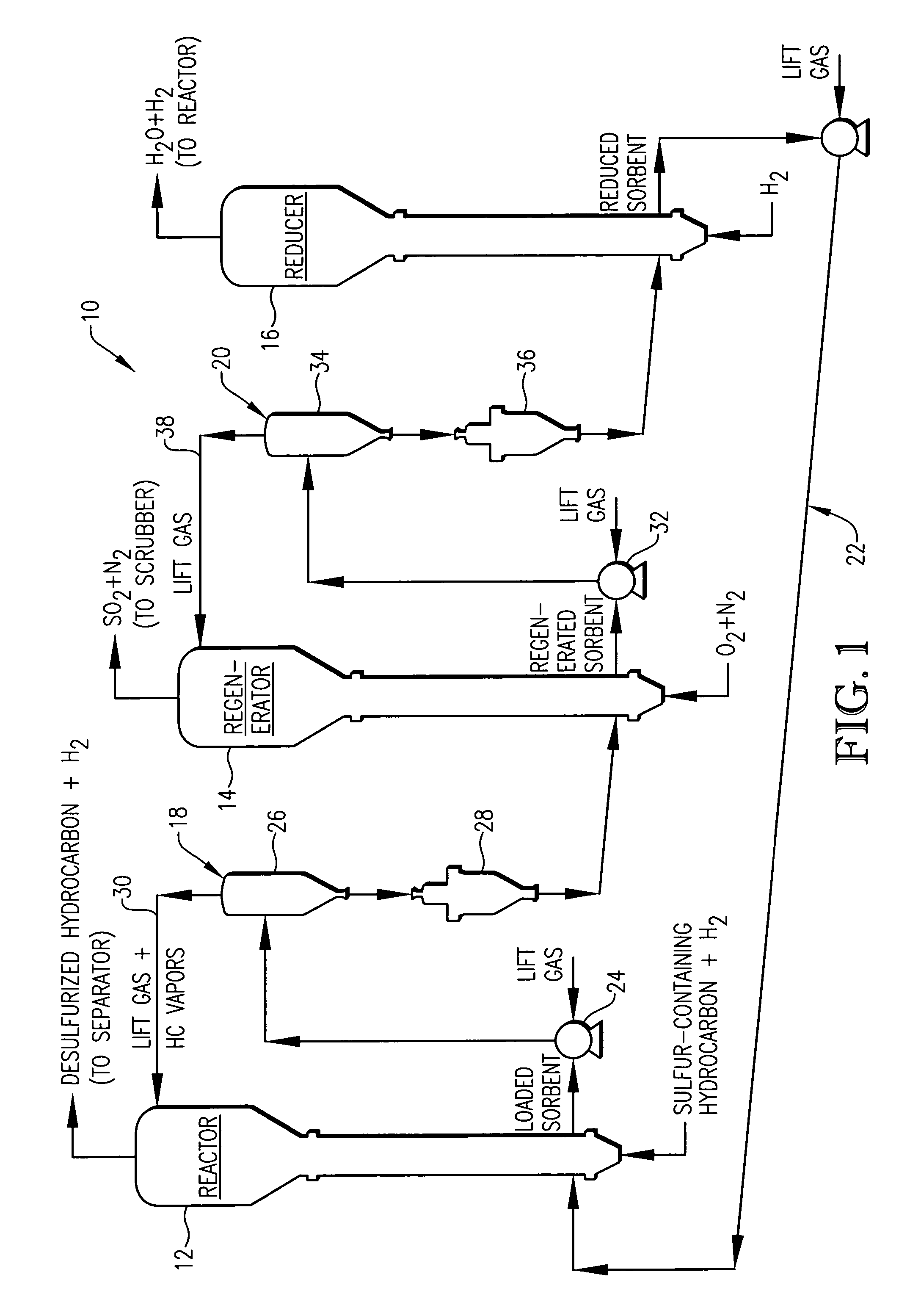
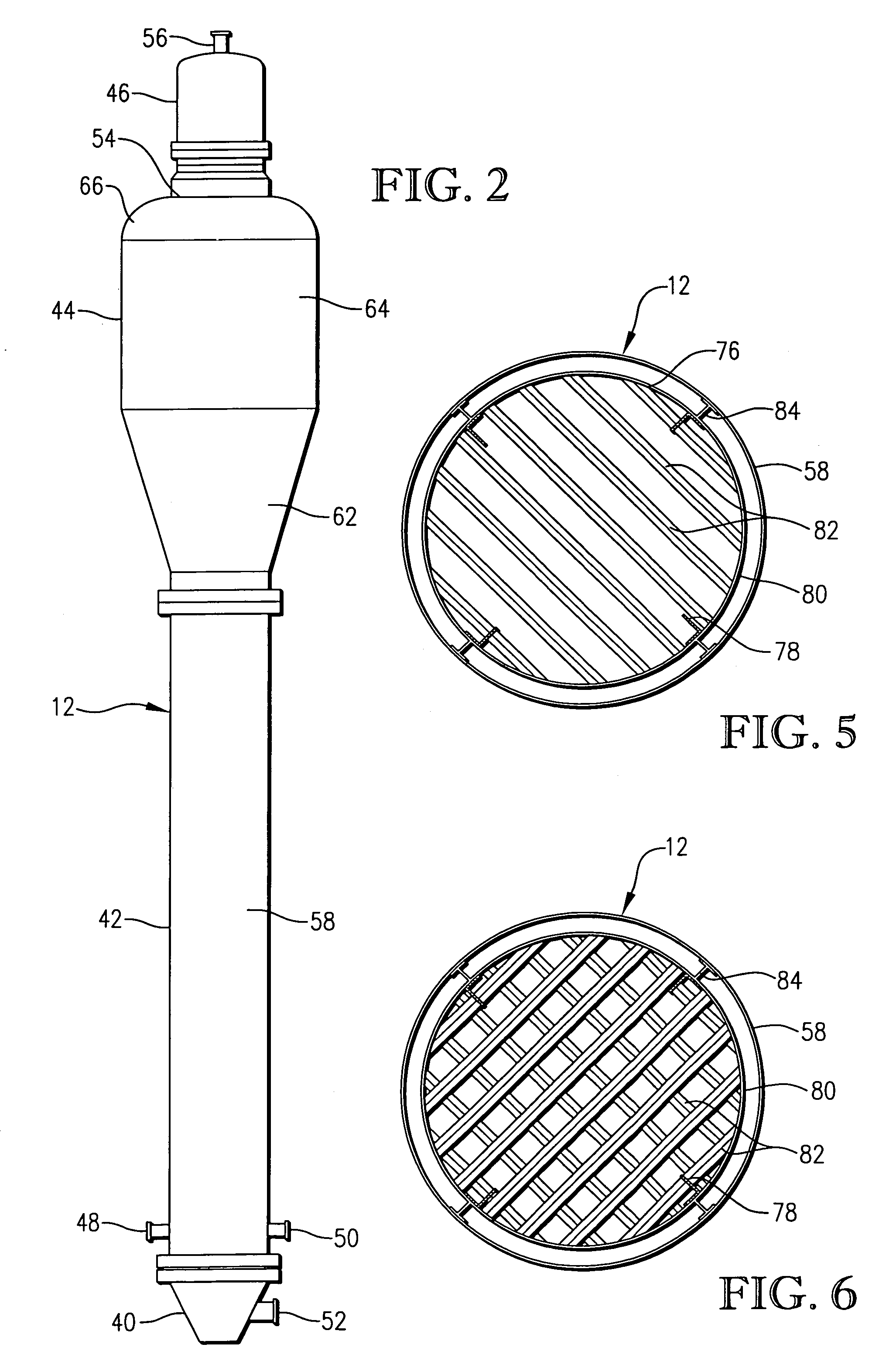
The present invention provides a hydrocarbon desulfurization system that employs a fluidized bed reactor with enhanced contacting between hydrocarbon-containing fluid stream and solid sorbent particles, thereby enhancing desulfurization of the hydrocarbon-containing fluid stream. The system minimizes octane loss and hydrogen consumption while providing enhanced sulfur removal. The system includes a fluidized bed reactor with contact-enhancing members, a regenerator for regenerating the sulfur-loaded sorbent particles, and a reducer for reducing the unreduced promoter metal component. The system also includes a desulfurization process involving contacting the hydrocarbon-containing fluid stream with finely divided solid sorbent particles, simultaneously contacting at least a portion of the hydrocarbon-containing stream and the sorbent particles with a series of substantially horizontal, vertically spaced baffle groups, contacting the sulfur-loaded sorbent particles with an oxygen-containing regeneration stream, and contacting the regenerated sorbent particles with a hydrogen-containing reducing stream.

Problems solved by technology

High levels of sulfurs in such automotive fuels is undesirable because oxides of sulfur present in automotive exhaust may irreversibly poison noble metal catalysts employed in automobile catalytic converters.
However, most conventional sulfur removal processes, such as hydrodesulfurization, tend to saturate olefins and aromatics in the cracked-gasoline and thereby reduce its octane number (both research and motor octane number).
In removing sulfur from diesel fuel by hydrodesulfurization, the cetane is improved but there is a large cost in hydrogen consumption.
However, the gas flow in fluidized bed reactors is often difficult to describe, with possible large deviations from plug flow leading to gas bypassing, solids backmixing, and inefficient gas / solids contacting.
Such undesirable flow characteristics within a fluidized bed reactor ultimately leads to a less efficient desulfurization process.

Method used


Image

  • Desulfurization in turbulent fluid bed reactor
  • Desulfurization in turbulent fluid bed reactor
  • Desulfurization in turbulent fluid bed reactor

Examples


example

Materials and Methods

[0063]This example provides data as to the efficacy of the invention claimed herein as compared to the prior art. In order to test the hydrodynamic performance of a full-scale desulfurization reactor, a full-scale one-half round test reactor 100, shown in FIG. 7, was constructed. The test reactor 100 was constructed of steel, except for a flat Plexiglass face plate which provided visibility. The test reactor 100 comprised a plenum 102 which was 44 inches in height and expanded from 24 to 54 inches in diameter, a reactor section 104 which was 35 feet in height and 54 inches in diameter, an expanded section 106 which was 8 feet in height and expanded from 54 to 108 inches in diameter, and a dilute phase section 108 which was 4 feet in height and 108 inches in diameter. A distribution grid having 22 holes was positioned in reactor 100 proximate the junction of the plenum 102 and the reactor section 104. The test reactor 100 also included primary and secondary cyclo...


PUM

PropertyMeasurementUnit
sizeaaaaaaaaaa
temperatureaaaaaaaaaa
mean particle sizeaaaaaaaaaa

Abstract

A method and apparatus for removing sulfur from a hydrocarbon-containing fluid stream wherein desulfurization is enhanced by improving the contacting of the hydrocarbon-containing fluid stream and sulfur-sorbing solid particulates in a fluidized bed reactor.

Description

BACKGROUND OF THE INVENTION[0001]This invention relates to a method and apparatus for removing sulfur from hydrocarbon-containing fluid streams. In another aspect, the invention concerns a system for improving the contacting of a hydrocarbon-containing fluid stream and sulfur-sorbing solid particulates in a fluidized bed reactor.[0002]Hydrocarbon-containing fluids such as gasoline and diesel fuels typically contain a quantity of sulfur. High levels of sulfurs in such automotive fuels is undesirable because oxides of sulfur present in automotive exhaust may irreversibly poison noble metal catalysts employed in automobile catalytic converters. Emissions from such poisoned catalytic converters may contain high levels of non-combusted hydrocarbons, oxides of nitrogen, and / or carbon monoxide, which, when catalyzed by sunlight, form ground level ozone, more commonly referred to as smog.[0003]Much of the sulfur present in the final blend of most gasolines originates from a gasoline blendin...

Claims


Application Information

Patent Timeline
Patent Type & Authority Patents(United States)
IPC IPC(8): C10G45/02
CPCB01J8/34C10G25/09C10G25/12B01J2219/00006B01J8/1872B01J8/26B01J2208/0084B01J2208/00991B01J8/18C10G25/00
Inventor MEIER, PAUL F.THOMPSON, MAX W.HOOVER, VICTOR G.GERMANA, GUIDO R.
Owner CHINA PETROCHEMICAL CORP
Learn More