
Electrical connector having plug and socket components

a technology of electrical connectors and components, applied in the direction of coupling device connections, coupling device details, coupling/disassembly of coupling parts, etc., can solve the problems of requiring a large amount of time, and requiring a large amount of screwing operation to fasten two screw threads of relatively long length, so as to reduce the number of turns and less thread length

Inactive Publication Date: 2009-02-17
WEIDMULLER INTERFACE GMBH & CO KG
View PDF12 Cites 14 Cited by
  • Summary
  • Abstract
  • Description
  • Claims
  • Application Information

AI Technical Summary

Benefits of technology

The present invention provides a plug and socket connector arrangement with a fastening sleeve that can be easily and securely assembled, even in difficult installation situations. The screw thread means on the sleeve have fewer turns and less thread length than the corresponding internal and external thread means of the socket, reducing the number of turns required to fasten the sleeve to the socket. The connector arrangement also includes a resilient O-ring that helps to secure the plug in the socket.

Problems solved by technology

Such designs have the drawback that after bringing the plug and socket parts together, a time-consuming screwing operation is required to fasten two screw threads of relatively long length.
This requires an appreciable amount of time, especially during the automated production of products requiring a large number of screwing operations.
The connections are arranged in close proximity, and this also contributes to the time delay and results in relatively laborious functions.
Unfortunately, this results in the disadvantage that the prior art designs require a costly fabrication and processing of both the sleeve part as well as also the socket.
In this case, if a connection were to be made to an internal screw thread, one cannot achieve any appreciable time advantage when compared to the known screwing procedures.
This construction is subject to criticism because of its relatively complicated and costly structure.

Method used


Image

  • Electrical connector having plug and socket components
  • Electrical connector having plug and socket components
  • Electrical connector having plug and socket components

Examples


Embodiment Construction

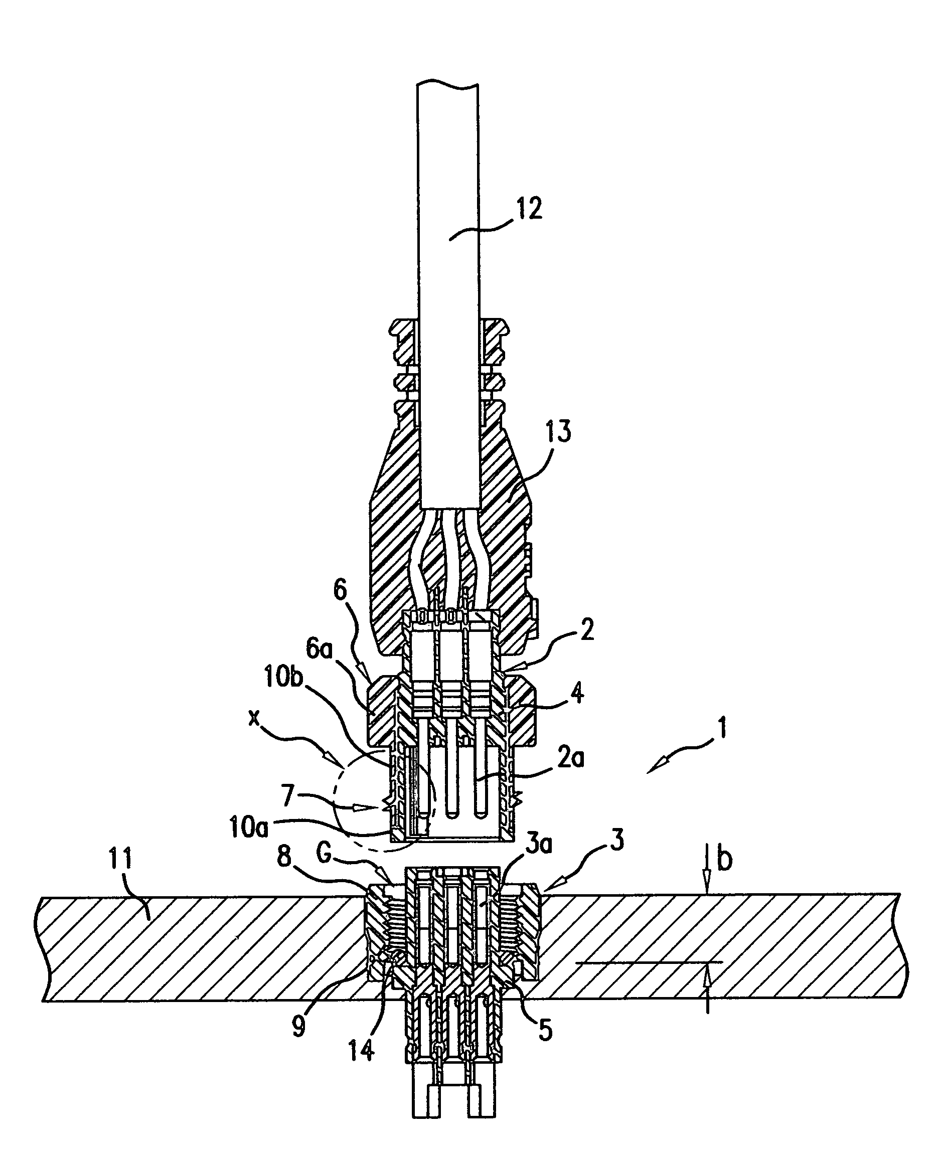
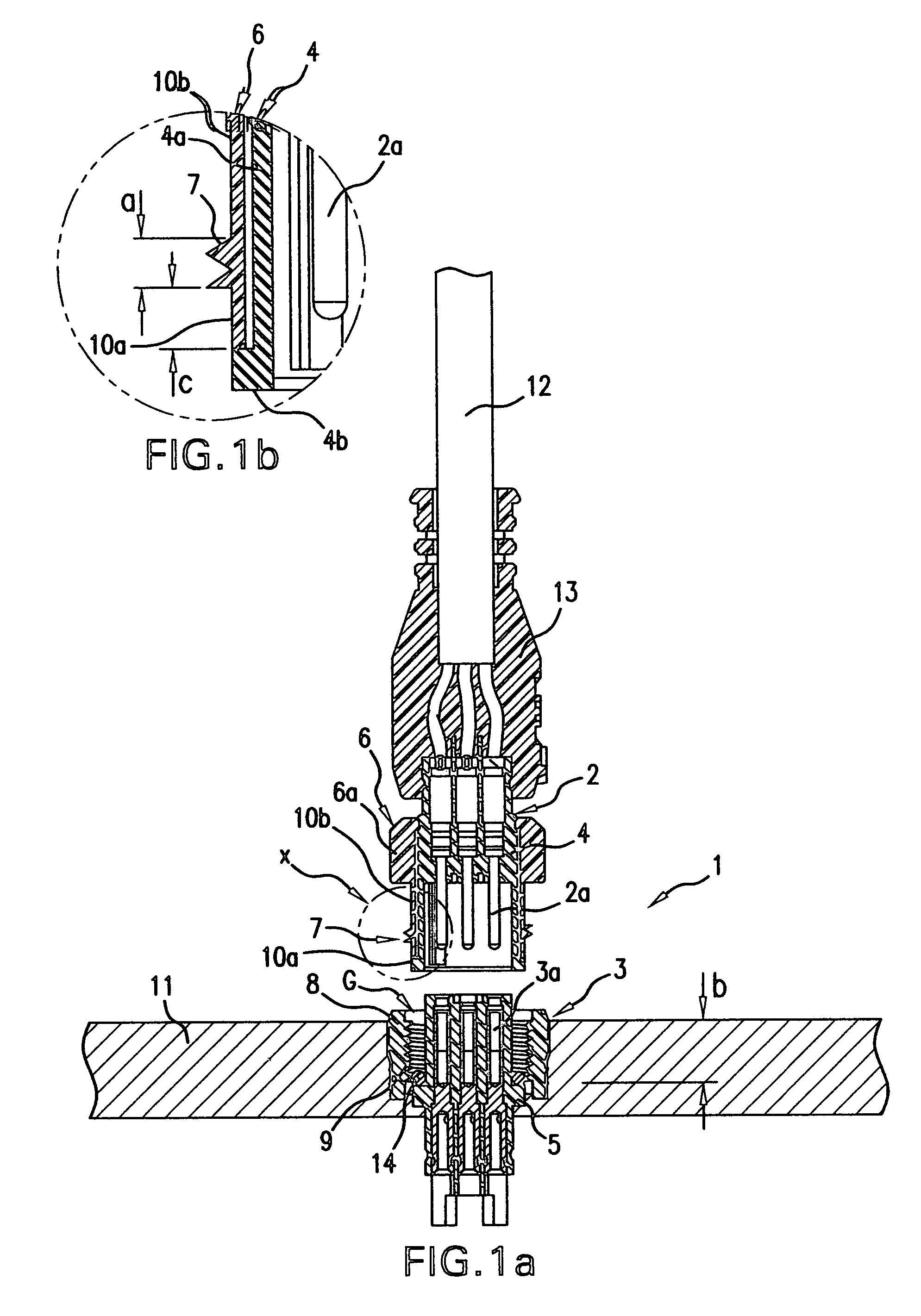
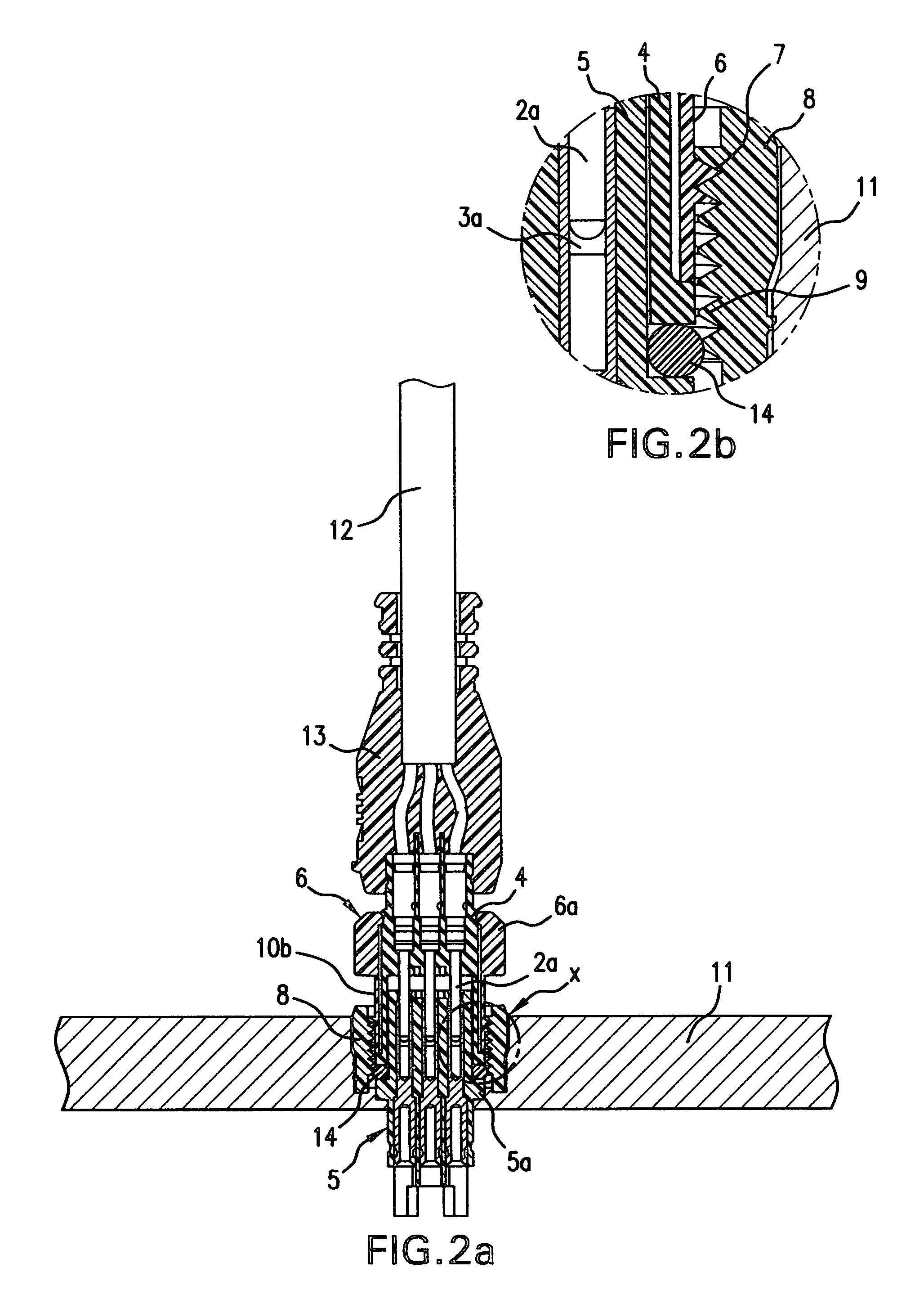
[0018]Referring first more particularly to FIG. 1a, the connector arrangement 1 of the present invention includes a plug 2 that is arranged for axial connection with a socket 3 that is mounted within and opening contained in a fixed support 11, such as the housing of an electrical apparatus. The plug includes a cylindrical inner body portion 4 formed from a suitable electrically insulating synthetic plastic material, which body portion contains a plurality of through bores in which are respectively mounted a plurality of male pin contacts 2a. The plug also includes an integral tubular portion 4a that extends coaxially from one end of the plug body. The plug is provided with a cable protecting device 13 that surrounds and protects the conductors that extend from the cable 12 to the respective male contacts 2a.

[0019]The socket 3 is formed from a suitable electrically insulating synthetic plastic material and includes a central cylindrical portion 5 containing a plurality of through b...


PUM


Abstract

An electrical connector arrangement includes a socket having a central body portion supporting a plurality of female contacts, and a tubular outer portion extending in concentric spaced relation about the body portion to define a groove. A plug component having a cylindrical body portion including a plurality of male contacts includes a tubular end portion that extends axially within the groove to connect the male and female contacts, respectively. A fastening sleeve is rotatably mounted on the plug between the outer surface thereof and the socket outer portion, whereby external screw threads on the sleeve engage internal threads on the socket tubular portion, thereby to fasten together the plug and socket components. In order to reduce the assembly time, the number and length of the screw threads on one of the sleeve and socket components is less than the number and length of the screw threads of the other component.

Description

BACKGROUND OF THE INVENTION[0001]1. Field of the Invention[0002]A plug and socket connector arrangement includes a fastening sleeve rotatably mounted on the plug between the outer surface thereof and a concentrically arranged outer annular portion of the socket, whereby external screw threads on the sleeve engage internal threads on the socket annular portion, thereby to fasten together the plug and socket components. In order to reduce the assembly time, the number and length of the screw threads on one of the sleeve and socket components is less than the number and length of the screw threads of the other component.[0003]2. Description of Related Art[0004]Various types of plug and socket electrical connectors are well known in the prior art. On the one hand, cables can be connected directly together by plug and socket connectors. Furthermore, it is possible, depending on the model, to connect a number of cables by means of plugs to a distributor which electrically connects the cab...

Claims


Application Information

Patent Timeline
Patent Type & Authority Patents(United States)
IPC IPC(8): H01R13/62
CPCH01R13/622H01R13/74H01R43/24
Inventor FEHLING, STEFANOESTERHAUS, JENS
Owner WEIDMULLER INTERFACE GMBH & CO KG
Learn More