
Method of detecting when electrode pads have been handled or removed from their package

a technology of electrode pads and packaging, applied in the field of electrodes, can solve the problems of wasting precious time and taking much longer

Active Publication Date: 2009-02-10
KONINK PHILIPS ELECTRONICS NV
View PDF7 Cites 11 Cited by
  • Summary
  • Abstract
  • Description
  • Claims
  • Application Information

AI Technical Summary

Benefits of technology

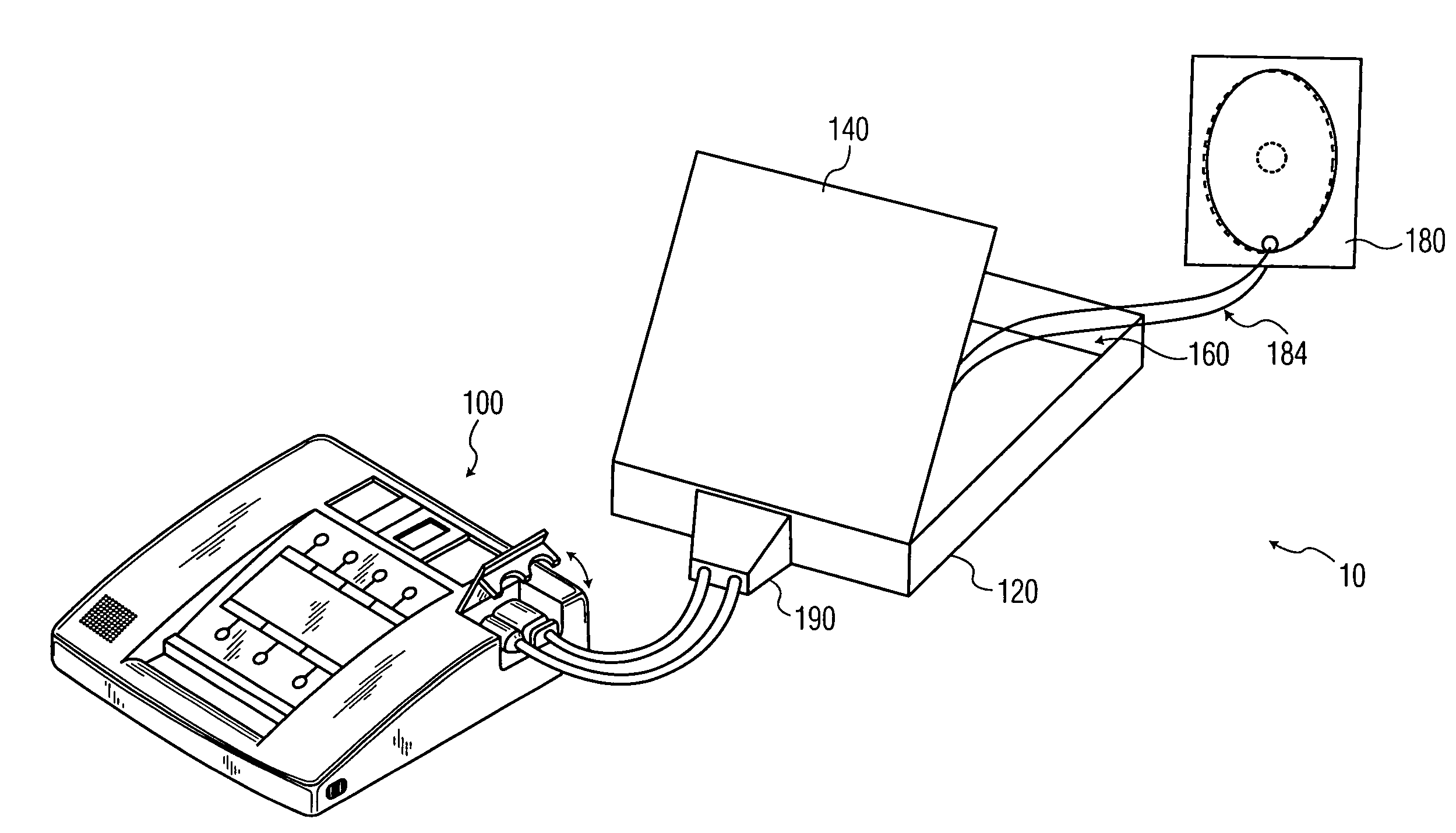
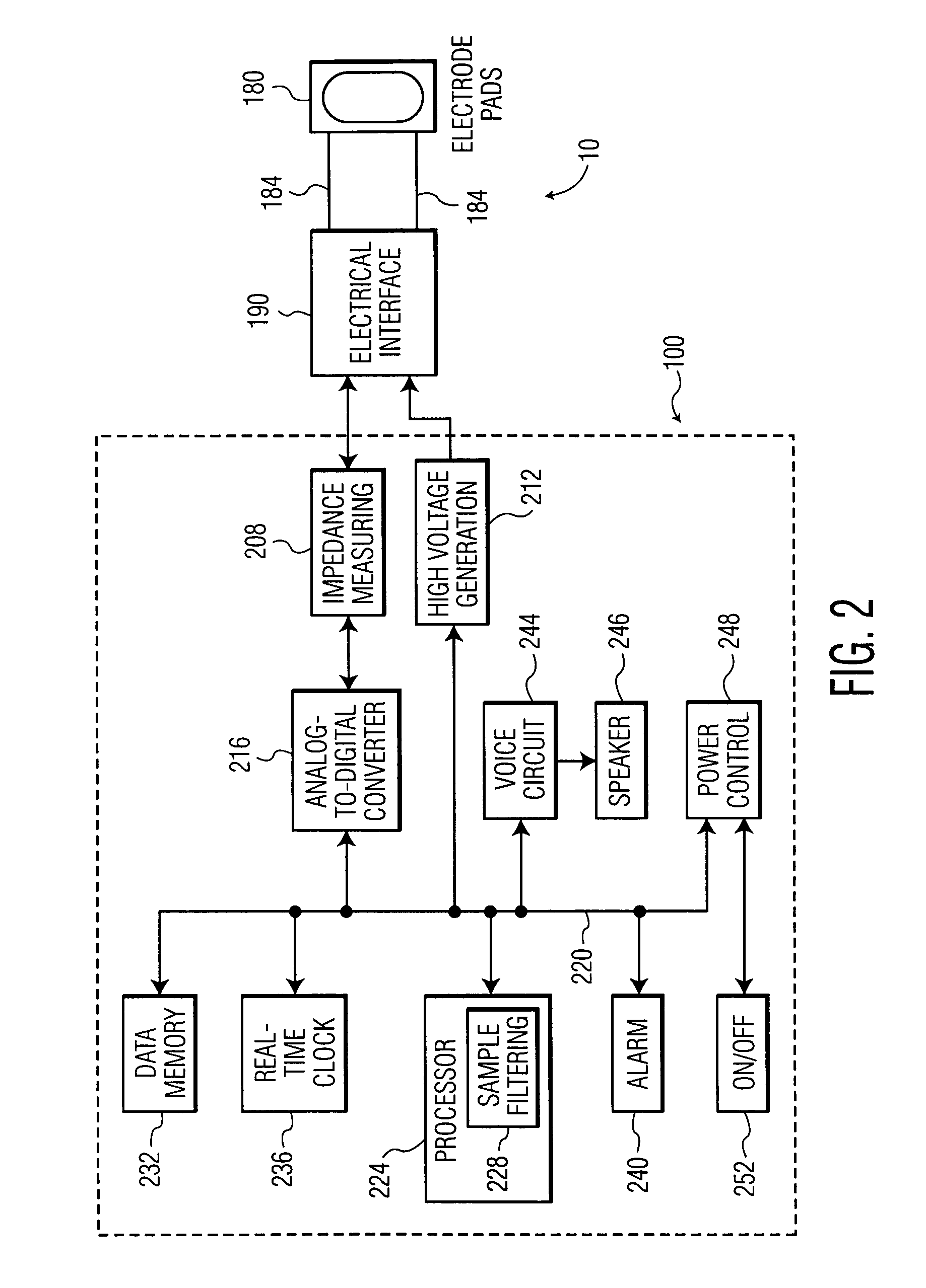
The invention is about a method for advancing the voice prompts of an automated external defibrillator (AED) during a cardiac arrest. The method uses pre-connected electrode pads that have been electrically attached to the AED and are ready for immediate deployment. The impedance of the pads is monitored continuously to detect changes that may occur when the pads are being manipulated by the user. This allows the AED to advance the voice prompts only when the user is ready to proceed to the next step, without additional input. The technical effect of this invention is to improve the usability and efficiency of AEDs by automatically advancing the voice prompts and guiding the user through the process of applying the pads to the patient's chest.

Problems solved by technology

For example, removing the clothes to bare the patient's chest might be a quick process if the patient is only wearing a tee-shirt, but will take much longer if there are multiple layers that need removing or cutting away.
The challenge lies in how the AED detects when the current action has been completed.
If the button is not pressed, the voice prompts do not proceed and precious time is lost while the user tries to determine the cause of the delay.

Method used


Image

  • Method of detecting when electrode pads have been handled or removed from their package
  • Method of detecting when electrode pads have been handled or removed from their package
  • Method of detecting when electrode pads have been handled or removed from their package

Examples


first embodiment

[0050]FIG. 4 is a cross-sectional view depicting a first embodiment for enhancing impedance variability for a packaged pair of electrodes 404 in accordance with the present invention. The packaged pair 404 includes two electrode pads 180 and an intervening electrically nonconductive element 408, preferably an electrically non-conducting, non-stick release layer such as silicon-coated paper, polyester, polypropylene, polyethylene, and / or other non-stick materials. Release layer 408 mates the two electrode pads 180 and has an opening 410. The package 412 of the packaged pair 404 surrounds the pads 180 and the release layer 408. The package 412 can be made of flexible plastic or other flexible material or may be, rigid and implemented as the electrode compartment 160 of the AED 100 for example. The electrode pad 180 has an electrode 416 which is shown to be a circular or oval shaped ring having a void or an opening 420 aligned adjacent to a release layer opening 424. Between the electr...

second embodiment

[0056]FIG. 5 is a cross-sectional view of a second embodiment for enhancing the impedance variability for the packaged pair of electrodes 404 in accordance with the present invention. The outer surface 440 of the foam layer 428 is joined to a portion 442 of the inside surface 444 of the package 412. The joinder can be accomplished by insertion of a piece of 2-sided tape 446. Alternatively, the adhesive swatch 446 may be hydrogel or a multi-layered film of pressure-sensitive adhesive or other substrates designed to adjust the adhesive and release properties of each side of the film. If the package 412 is rigid, e.g. the electrode compartment 160, the tape 446 is placed to adhere the bottom electrode pad 180 to the compartment.

[0057]As in the first embodiment, the hole(s) 410 in the release layer 408 allows the hydrogel from the first pad 180 to touch the hydrogel of the second pad 180, creating an electrical connection between the pads. Once this electrical connection is established,...

third embodiment

[0059]FIG. 6 depicts a third embodiment for enhancing impedance variability for the package pair of electrodes 404 in accordance with the present invention. A packaged electrode pad pair 404 and its accompanying lead wires 184 are held within the compartment 160 by two belts or straps 604 that mutually and adhesively attach end-to-end to surround the pair and which attach at their other ends to the compartment, which in turn surrounds the belts and the pads. The end-to-end attachment 608 is configured with an adhesive strength having a magnitude small enough to allow an operator to manually separate the belts to apply the pads 180 to a medical patient in need of defibrillation. As the user pulls the pads 180 out of their package, the straps 604, which can be made of paper, plastic, or even a thin metal foil, hold the pads and causes them to bend. The belts 604 are preferably placed around the middle of the pad pair 404, so that the bending occurs over the hole(s) 410 in the release ...


PUM


Abstract

Handling or removal of a pair of pre-connected defibrillator electrode pads from their package, or a compartment in the defibrillator, is detected in order to effectively time the issuance of prompts to guide the user. Detection occurs when an impedance level between the electrode pads varies sufficiently over time to indicate occurrence of the handling or removal event. The pads are preferably configured to leverage variability in the impedance that results from bending of pads during handling or removal.

Description

CROSS REFERENCE TO RELATED APPLICATION[0001]This application claims the benefit of U.S. provisional application Ser. No. 60 / 483,197 filed Jun. 27, 2003, which is incorporated herein.BACKGROUND OF THE INVENTION[0002]1. Field of the Invention[0003]The present invention relates to electrodes, and, more particularly, to monitoring electrodes.[0004]2. Discussion of the Prior Art[0005]In the US alone, over 350,000 people die annually from Sudden Cardiac Arrest. Many of these victims have no prior warning of heart disease, and 70% die outside the hospital. The only treatment for an SCA victim is to provide an immediate, high-energy electric shock through the heart. Minimizing the time to first shock is critical since, for every minute after 4 minutes, the chances of resuscitation decrease by 10%. If a shock is not applied within 10 minutes, the chances of resuscitation are almost zero.[0006]U.S. Pat. No. 5,700,281, issued on Dec. 23, 1997, hereinafter “the '281 patent,” the entire disclosu...

Claims


Application Information

Patent Timeline
Patent Type & Authority Patents(United States)
IPC IPC(8): A61N1/00A61N1/04A61N1/08A61N1/39
CPCA61N1/046A61N1/0472A61N1/3968A61N1/0492A61N1/08A61N1/3931A61N2001/37294
Inventor DENNEY, DOUGLASLYSTER, THOMASDIEDERICHS, JOSEPHKINGSBURY, DANIELJONSEN, ERICGREENSTEIN, ALANSOLOSKO, THOMAS A.POWERS, DANIEL J.
Owner KONINK PHILIPS ELECTRONICS NV
Learn More