
Methods, system, and program product for the detection and correction of spherical aberration

a technology of spherical aberration and program products, applied in the field of optical systems, can solve the problems of spherical aberration not being detected, spherical aberration being more problematic in spherical lenses, and common problems such as spherical aberration,

Active Publication Date: 2009-02-10
MEDIA CYBERNETICS
View PDF5 Cites 10 Cited by
  • Summary
  • Abstract
  • Description
  • Claims
  • Application Information

AI Technical Summary

Benefits of technology

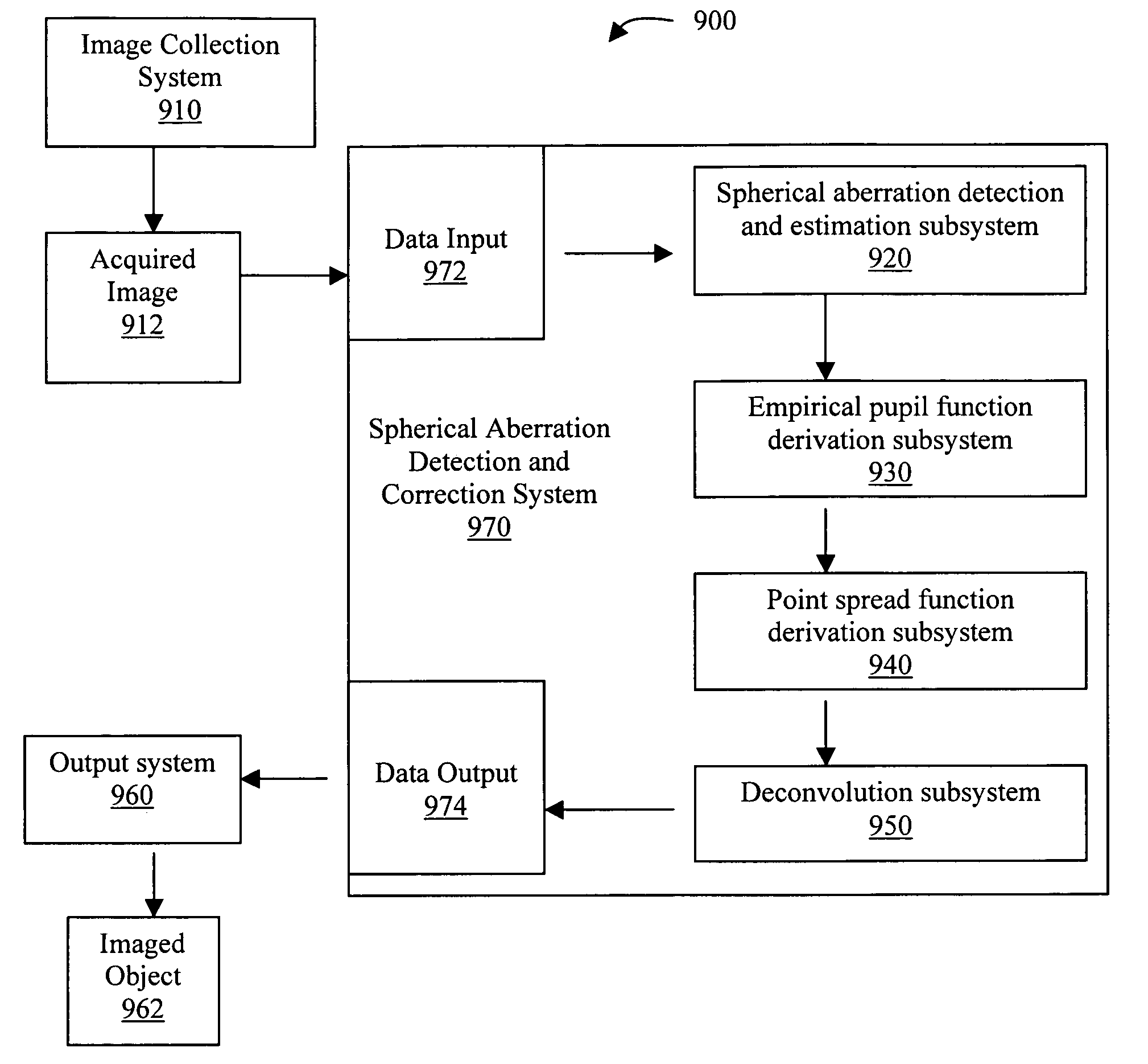
"The present invention provides a method, system, and program product for detecting and correcting spherical aberration in microscopy systems. The invention automatically detects the coefficient for spherical aberration, derives a pupil function, and uses a robust deconvolution algorithm that incorporates the derived PSF value. The technical effects of the invention include improved image quality, reduced blurring, and improved depth of field."

Problems solved by technology

Spherical aberration is a common problem in microscopy systems.
Spherical aberration is more problematic in spherical lenses.
Lenses having parabolic surfaces have been shown to reduce or eliminate the effect of spherical aberration, but are not often used, due to their great expense.
The difficulty with such methods, aside from the additional time and expense they require, is that spherical aberration often is not detected until after image data have been collected.
Because sampling density is determined by a user when acquiring data, the Nyquist criterion may not be satisfied.
A further difficulty in using equation 2 to calculate a PSF is that it assumes that PSFs are symmetric.
Aberrations can cause a PSF to be asymmetric.
In practice, however, none of the schemes mentioned above has proved satisfactory in correcting spherical aberration.
PSFs constructed according to diffraction theory are generally not accurate; measured PSFs are difficult to obtain and unreliable; PSFs estimated concurrently with an estimation of the imaged object do not follow accurate parametric modeling of the PSF; and parametric blind deconvolution is prohibitively slow and requires enormous computing power.

Method used


Image

  • Methods, system, and program product for the detection and correction of spherical aberration
  • Methods, system, and program product for the detection and correction of spherical aberration
  • Methods, system, and program product for the detection and correction of spherical aberration

Examples


Embodiment Construction

A. Spherical Aberration Detection

[0059]As noted above, users of microscopy systems are often unaware of the presence of spherical aberration during the collection of image data and may sometimes remain unaware that the data are so affected. Accordingly, one objective of the present invention is the detection of spherical aberration in image data.

[0060]Two novel methods for detecting spherical aberration are provided. The first is a correlation-based method. The second is an energy minimization method.

1. Correlation Method

[0061]The correlation-based method is predicated on the fact that if a spherically aberrated point spread function (PSF) is generated correctly and approximately the same as the true PSF, then similar structures are likely to be observed both in the spherically aberrated image data and in the reconstructed PSF. Therefore, the correlation-based method of the present invention first requires the generation of a plurality of spherically aberrated PSFs, each employing a...


PUM


Abstract

The present invention provides methods, a system, and a program product for the rapid detection and correction of spherical aberration in microscopy systems. More specifically, the present invention empirically derives a pupil function, adaptively corrects PSF parameters, and automatically detects the coefficient for spherical aberration. A first aspect of the invention provides a method for detecting and estimating spherical aberration in an acquired image obtained using an optical system, comprising the steps of deconvolving an image using each of a plurality of point spread functions, wherein each point spread function has a different spherical aberration value, calculating an image energy for each deconvolved image, and choosing as a spherical aberration coefficient the spherical aberration value corresponding to the deconvolved image having the lowest image energy, wherein a spherical aberration coefficient other than 0 indicates the presence of spherical aberration in the acquired image and its distance from 0 is an estimation of the degree and direction of spherical aberration.

Description

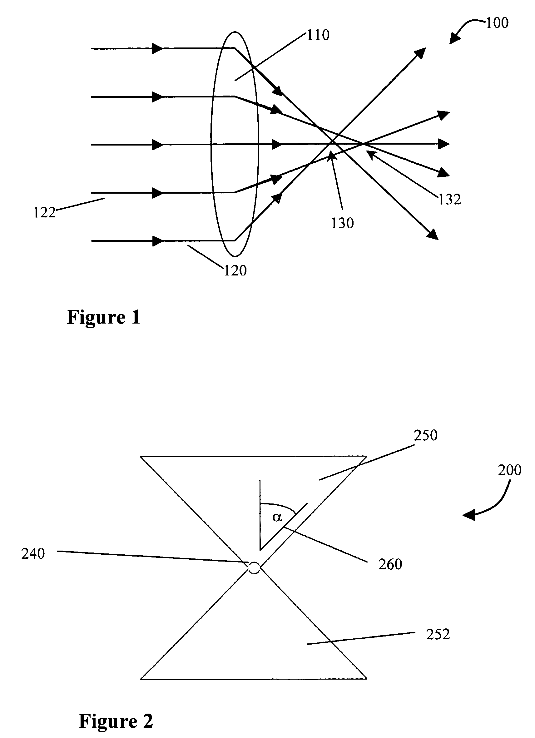
CROSS REFERENCE TO RELATED APPLICATIONS[0001]The current application claims the benefit of co-pending U.S. Provisional Application No. 60 / 508,735, filed Oct. 3, 2003, which is hereby incorporated herein by reference.BACKGROUND OF THE INVENTION[0002](1) Technical Field[0003]The present invention relates generally to optical systems and more specifically to methods, systems, and program products for the detection and correction of spherical aberration in microscopy systems.[0004](2) Related Art[0005]Spherical aberration is a common problem in microscopy systems. It is the result of differences in the focal points of light rays based on their differing distances from the center of a lens, i.e., the optic axis of the lens. In the apparatus 100 shown in FIG. 1, light rays 120 passing through a lens 110 at points further from its center have a focal point 130 closer to lens 110 than the focal point 132 formed by light rays 122 entering lens 110 at points closer to its center. Often, this ...

Claims


Application Information

Patent Timeline
Patent Type & Authority Patents(United States)
IPC IPC(8): G06K9/40G06K9/64G01B9/00G02B21/36G02B27/00
CPCG02B21/365G02B27/0025
Inventor ASAD, ABU-TARIFHOLMES, TIMOTHY J.
Owner MEDIA CYBERNETICS
Learn More