
Measuring system for contactless detection of a rotary angle, with a magnetic-field-sensitive element disposed in a recess of the magnet

a magnetic field sensitive element and measurement system technology, applied in the direction of measuring devices, instruments, devices using electric/magnetic means, etc., can solve the problems of large changes in voltage in the output signal of electronics, large magnets used in such applications, etc., to reduce the influence of extraneous fields and tolerances, the effect of reducing the resolution and linearity of the measurement signal

Active Publication Date: 2009-02-10
ROBERT BOSCH GMBH
View PDF7 Cites 11 Cited by
  • Summary
  • Abstract
  • Description
  • Claims
  • Application Information

AI Technical Summary

Benefits of technology

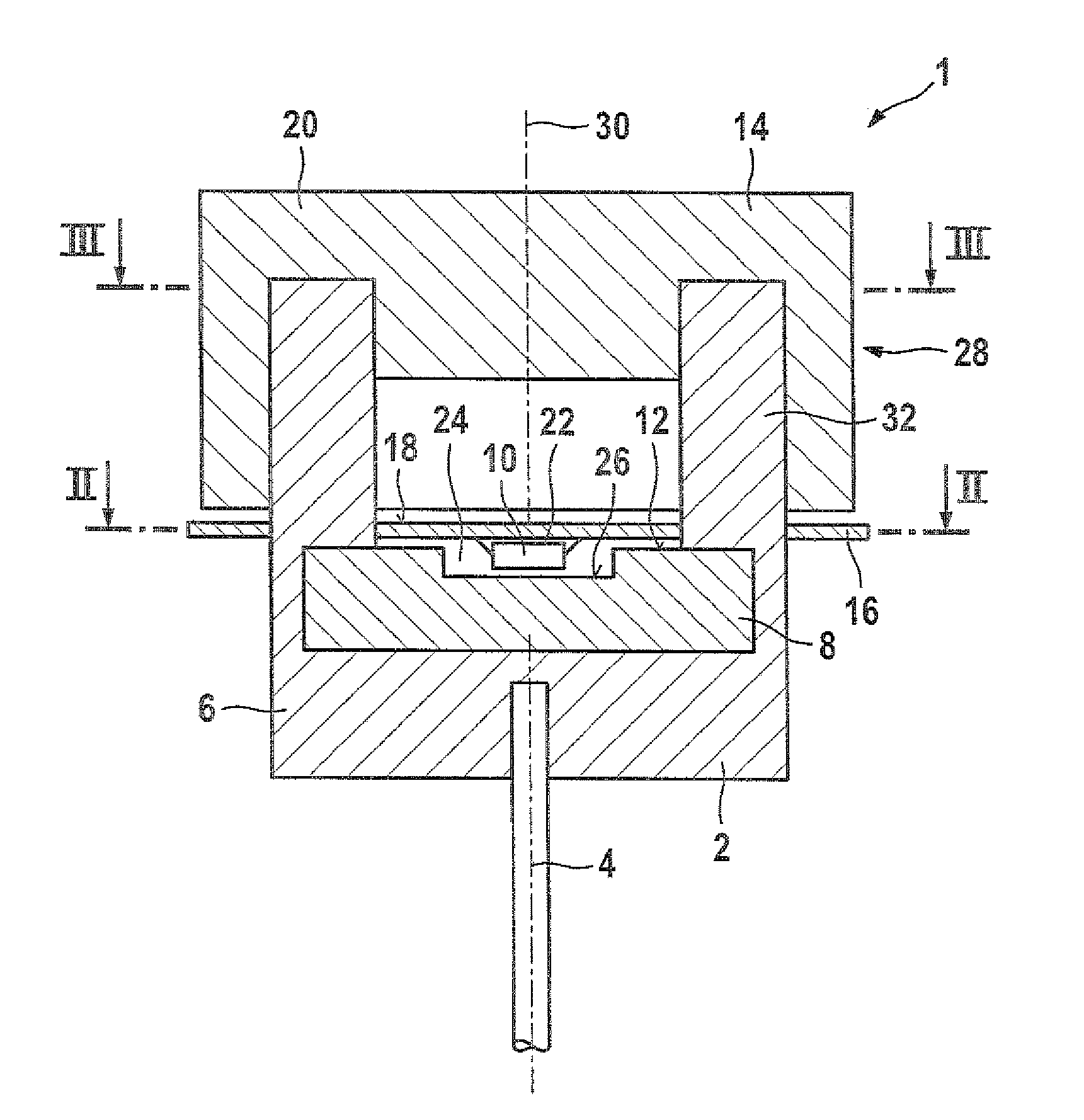
[0011]The invention is based on the concept that the magnetic-sensitive element protrudes at least partway into the blind-borelike recess of the magnet. As a result, the magnetic-field-sensitive element is in an embedded position in the magnet and is thus reached by a range of the magnetic field where this field is homogeneous and the magnetic field lines occur in concentrated form. Consequently, with a relatively small magnet, a relatively strong, homogeneous magnetic field can be generated, which has a favorable effect on the resolution and linearity of the measurement signal. As a result, the influence of extraneous fields and tolerances is reduced as well.
[0012]In a preferred embodiment, the magnet is held on the rotor via a magnet holder that is supported rotatably on the stator by a guide. As a result, the magnet is centered relative to the magnetic-field-sensitive element and vice versa, so that any existing play in the rotary bearing action of the rotor can be compensated for. This improved guidance provides for an advantageous increase in measurement precision.
[0014]In a further provision, the magnetic-field-sensitive element has a spacing from a bottom of the recess of the magnet that is so small that the magnetic-field-sensitive element is just barely not in contact with this bottom. This provides for further improvement in the position of the magnetic-field-sensitive element relative to the magnet, since a spacing that is as slight as possible yet without causing a magnetic short circuit ensures even better flooding of the magnetic-field-sensitive element by the magnetic field.
[0015]Last but not least, the magnet is disklike and magnetized or polarized in sectors on the surface pointing toward the magnetic-field-sensitive element. The edges of the recess in the magnet are then polarized oppositely, as a result of which the field lines of the magnetic field occur in concentrated form in the region of the recess and extend approximately parallel to the bottom of the recess and hence also parallel to he magnetic-field-sensitive element. If this latter element is formed by a Hall element, then it preferably has a magnetic field concentrator. This is because Hall elements are sensitive to the component of the magnetic field B that strikes their surface at a right angle, as has already been discussed at the outset. The magnetic field concentrator varies the course in its vicinity of the field lines of the magnetic field B and causes the field lines, which in the absence of the magnetic field concentrator would extend parallel to the surface of the Hall element, to penetrate the Hall element virtually perpendicular to its surface, that is, in a direction in which this element is sensitive. In this way, the magnetic-field-sensitive element is optimally reached by the field lines of the magnetic field, which leads to further improvement in the resolution and a further enhancement of measurement precision.

Problems solved by technology

The magnets used in such applications are therefore relatively large.
In such applications, even small errors, in the range of from 0.1° to 0.3°, cause relatively major changes of voltage in the output signal in the electronics.

Method used


Image

  • Measuring system for contactless detection of a rotary angle, with a magnetic-field-sensitive element disposed in a recess of the magnet
  • Measuring system for contactless detection of a rotary angle, with a magnetic-field-sensitive element disposed in a recess of the magnet
  • Measuring system for contactless detection of a rotary angle, with a magnetic-field-sensitive element disposed in a recess of the magnet

Examples


Embodiment Construction

[0022]The preferred exemplary embodiment of a measuring system 1, shown in FIG. 1, for contactless detection of a rotational angle is used for instance to measure the actuation angle of an electronic accelerator pedal, not shown for reasons of scale, of an accelerator pedal module. Furthermore, a measuring system 1 of this kind can be used in various systems in the automotive field in which rotational angles have to be measured, such as in a throttle valve transducer, an accelerator pedal value transducer in a pedal module, a vehicle body suspension transducer, or an angle encoder of a windshield wiper drive mechanism.

[0023]The measuring system 1 includes a rotor 2, such as a disklike magnet holder 6 that is rotatable about an axis of rotation 4 and that is connected in a manner fixed against relative rotation to an accelerator pedal supported rotatably relative to a bearing block, and embedded in the magnet holder is a radially outer edge of a magnet 8, for instance of disklike sha...


PUM


Abstract

The invention relates to a measuring system for contactless detection of a rotational angle, having a first body on which at least one magnet is disposed and having at least one magnetic-field-sensitive element, supported by a second body, for generating a measurement signal, the first body and the second body being rotatable counter to one another about an axis of rotation, and the magnet having a blind-borelike recess. The invention provides that the at least one magnetic-sensitive element protrudes at least partway into the recess.

Description

REFERENCE TO FOREIGN PATENT APPLICATION[0001]This application is based on German Patent Application No. 10 2007 016 133.8 filed 29 Mar. 2007, upon which priority is claimed.BACKGROUND OF THE INVENTION[0002]1. Field of the Invention[0003]The invention relates to a measuring system for contactless detection of a rotational angle, having a first body on which at least one magnet is disposed and having at least one magnetic-field-sensitive element, supported by a second body, for generating a measurement signal, the first body and the second body being rotatable counter to one another about an axis of rotation, and the magnet having a blind-borelike recess.[0004]2. Description of the Prior Art[0005]A measuring system of the type with which this invention is concerned can be used in various systems in the automotive field in which rotational angles have to be measured, such as in a throttle valve transducer, an accelerator pedal value transducer in a pedal module, a vehicle body suspensi...

Claims


Application Information

Patent Timeline
Patent Type & Authority Patents(United States)
IPC IPC(8): G01B7/30
CPCG01D5/145G01D2205/80
Inventor BAUER, BERNHARDZEH, MATTHIASKOEBERLE, BERNDKLOTZBUECHER, THOMAS
Owner ROBERT BOSCH GMBH
Learn More