Column hole cover

a column hole cover and cover technology, applied in the field of column hole covers, can solve the problems of cumbersome and laborious operation for fixing the one end of the column hole cover to the instrument panel using bolts or the like, and achieve the effect of reducing labor involved in assembling the column hole cover and adequate sealing performan

Inactive Publication Date: 2009-02-03
MARUGO RUBBER IND +1
View PDF26 Cites 7 Cited by
  • Summary
  • Abstract
  • Description
  • Claims
  • Application Information

AI Technical Summary

Benefits of technology

[0008]According to the embodiment of the invention, the seal may be maintained in the pressure contact against the circumferential portion of the aperture of the instrument panel even if the steering gear box is displaced. Therefore, the seal can ensure an adequate sealing performance. Accordingly, the fixing of the column hole cover to the instrument panel by using a screw or the like is not required and hence, the labor involved in assembling the column hole cover can be reduced.

Problems solved by technology

However, an operation for fixing the one end of the column hole cover to the instrument panel using the bolt or the like is cumbersome and labor intensive.

Method used


Image

  • Column hole cover
  • Column hole cover
  • Column hole cover

Examples


Embodiment Construction

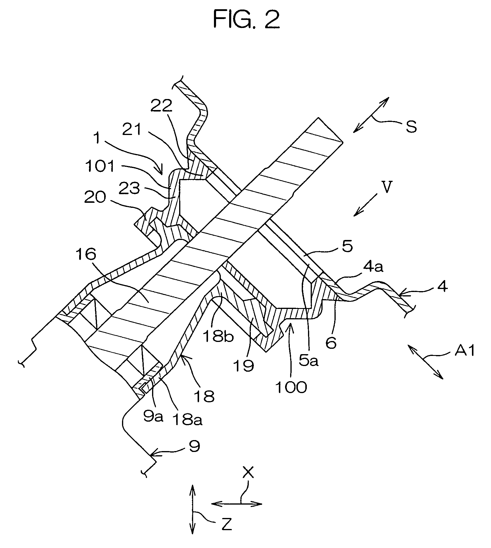
[0018]A column hole cover according to one embodiment of the present invention will hereinbelow be described with reference to the accompanying drawings. FIG. 1 is a schematic diagram showing a steering apparatus including the column hole cover according to one embodiment of the present invention.

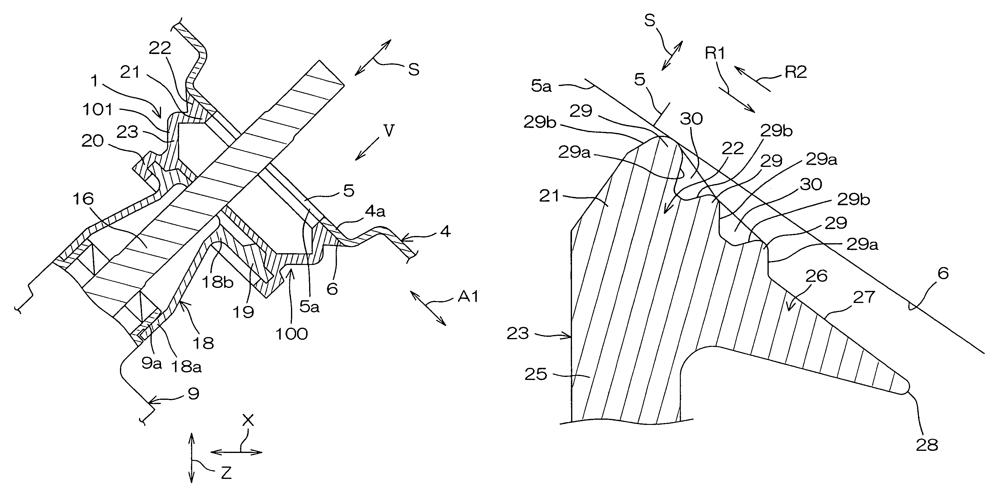
[0019]The column hole cover 1 is interposed between a circumferential portion 6 of an aperture 5a (shown in FIG. 2) of a column hole 5 and a steering gear box 9 of a steering mechanism 8 of a steering apparatus 7, the column hole 5 formed at a wall 4a (shown in FIG. 2) of an instrument panel 4 partitioning an engine room 2 and a cabin 3 of an automotive vehicle.

[0020]The steering apparatus 7 includes a steering shaft 11, to one end 11a of which a steering wheel 10 is mounted. The steering shaft 11 is rotatably supported by a vehicle body 14 via a steering column 12 and a bracket 13. The other end 11b of the steering shaft 11 is coupled to a pinion shaft 16 of the steering mechanism 8 via an...


PUM


Abstract

A column hole cover is interposed between a circumferential portion of an aperture of a column hole of an instrument panel and a steering gear box capable of being displaced in a predetermined direction. The column hole cover includes a cylindrical main body extended in the predetermined direction. The main body includes a first annular end portion directly or indirectly fixed to the steering gear box, and a second annular end portion. The second end portion is provided with an annular seal. An intermediate portion between the first and second end portions is provided with a expandable / contractible portion capable of being elastically expanded or contracted in the predetermined direction. Irrespective of the displacement of the steering gear box, the annular seal is maintained in an elastic pressure contact against the circumferential portion of the aperture of the instrument panel by a reaction force of the compressed expandable / contractible portion.

Description

BACKGROUND OF THE INVENTION[0001]1. Field of the Invention[0002]The present invention relates to a column hole cover which is used in automotive vehicles for covering a lower part of a column hole formed at an instrument panel for insertion of a steering column therethrough.[0003]2. Description of Related Art[0004]This type of column hole cover has a tubular shape. The column hole cover has one end thereof fixed to a steering gear box and the other end thereof fixed to a circumferential portion of an aperture of the column hole of the instrument panel via a fixing member such as a band, bolt or clip (see, for example, Japanese Unexamined Patent Publication No.11-78912(1999)). The other end of the column hole cover encloses the aperture of the column hole, thereby preventing muddy water from entering a cabin through the column hole.[0005]However, an operation for fixing the one end of the column hole cover to the instrument panel using the bolt or the like is cumbersome and labor int...

Claims


Application Information

Patent Timeline
Patent Type & Authority Patents(United States)
IPC IPC(8): B62D1/16B60R13/08B62D1/20F16J3/04F16J15/52
CPCB60R13/0846B62D1/16
Inventor SUZUKI, HIROHISAFURUKAWA, SEIZOUYAMAMOTO, NOBORUFUJIWARA, TERUYA
Owner MARUGO RUBBER IND
Why Eureka
Try Eureka