
Accelerated ray-object intersection

a ray object and intersection technology, applied in the field of ray object intersections, can solve the problems of inefficient finding, limited depth precision of hardware, and inability to obtain the nth-closest intersection or an arbitrary nth-closest intersection, etc., and achieve the effect of fast and accurate finding ray object intersections and easy computation

Active Publication Date: 2009-01-27
AUTODESK INC
View PDF9 Cites 44 Cited by
  • Summary
  • Abstract
  • Description
  • Claims
  • Application Information

AI Technical Summary

Benefits of technology

This approach enables quick and precise computation of ray-object intersections, maintaining accuracy with minimal computational overhead, even under transformations, and naturally conforms to the object's geometry, facilitating efficient determination of consecutive and unoccluded intersections.

Problems solved by technology

It is a well-known problem in the field of computer graphics to need to find the intersection between a ray and an object.
However, it is a nontrivial problem to efficiently find an intersection between a ray and a complex object such as a mesh surface, and in particular it is nontrivial to efficiently find the intersection that is closest to the origin of the ray.
There are several drawbacks to this prior art intersection technique.
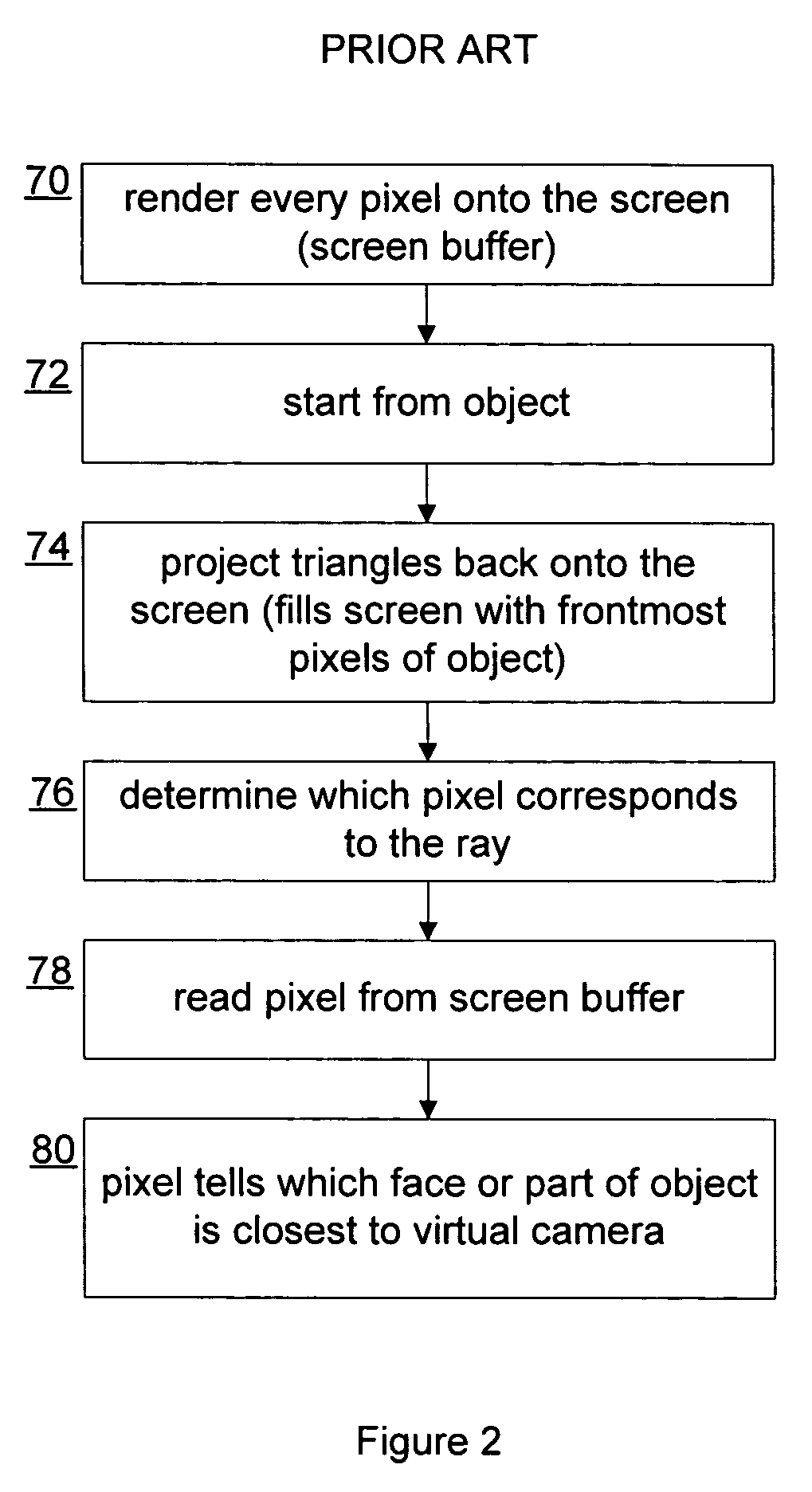
However, such hardware has limited depth precision, such as 16 or 24 bits, which may introduce depth precision artifacts for objects that are close to each other.
The prior art has not been able to obtain the N closest intersections to the ray's origin or an arbitrary Nth-closest intersection.
Nor has the prior art observed that this ability could be useful when working with transparent or semi-transparent surfaces.
This technique also has problems.
If the bounding box is subdivided 102 more than necessary, then memory use and performance will be adversely affected.
Inadequate subdividing 102 can result in insufficient resolution.

Method used


Image

  • Accelerated ray-object intersection
  • Accelerated ray-object intersection
  • Accelerated ray-object intersection

Examples


Embodiment Construction

[0040]The following definitions may assist the reader. A tessellation is a general subdivision of a spatial domain, where there is no implied maximum dimension. A triangulation is a connectivity scheme that is made up of triangular elements that tessellate a planar region.

[0041]A Delaunay triangulation is a triangulation that has the additional condition that the circumcircle uniquely defined by the three points on a face will not contain any other points in the domain. A constrained Delaunay triangulation forces specified edges into the triangulation, and adds new edges based on specific visibility and Delaunay criteria. A Delaunay tessellation is analogous to a Delaunay triangulation in the spatial domain. A tetrahedrization is a 3D tessellation that is made up of tetrahedrons. To tetrahedrize something is to construct a tetrahedrization. A polyhedrization is a tessellation of 3 or more dimensions made of polyhedrons of the same dimension. A line is a linear path either straight o...


PUM


Abstract

An original mesh is provided with a bounding surface and a convex hull surface. A first tessellation links the convex hull to the original mesh, and a second tessellation links the bounding surface to the convex hull. Using the tessellations to find a first intersection between a ray and the original mesh by finding a first intersected polygon of the bounding surface, and then traversing adjacent intersected polygons starting from the first intersection until the intersection is found. When the ray is moved, a second ray-surface intersection can be found by finding a polygon locally near the first intersection and containing a first intersection with the moved ray, traversing out from the local polygon through adjacent polygons intersected by the moved ray, and determining whether traversed polygons are unoccluded based on whether they are part of the convex hull surface.

Description

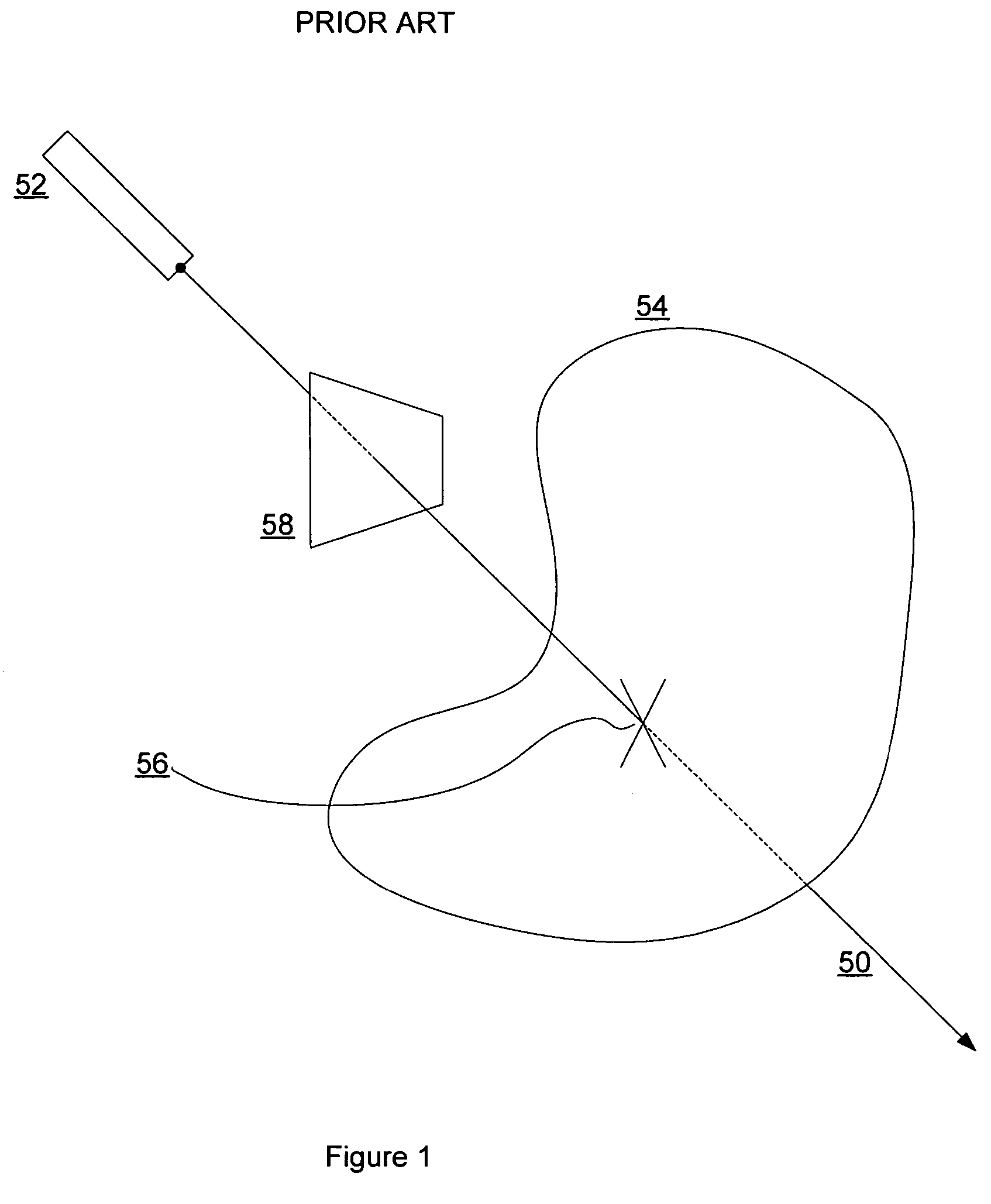
BACKGROUND OF THE INVENTION[0001]1. Field of the Invention[0002]The present invention is directed to a method, system, and data structure, for finding a ray-object intersection. More particularly, the present invention is directed to a lightweight polyhedrization data structure, using it to find an intersection, and using it to quickly find successive unoccluded or Nth-closest intersections when relatively minor movements of the ray or object occur relative to each other.[0003]2. Description of the Related Art[0004]FIG. 1 shows a ray 50 originating at a virtual camera or viewpoint 52 and intersecting an object 54 at an intersection 56. A screen buffer 58 is also shown. It is a well-known problem in the field of computer graphics to need to find the intersection between a ray and an object. Ray-object intersections are used for various applications such as ray-tracing, painting onto 3-D models, virtual space simulation such as collision detection, and so on.[0005]Finding an intersect...

Claims


Application Information

Patent Timeline
Patent Type & Authority Patents(United States)
IPC IPC(8): G06T17/00G06T17/20
CPCG06T15/06G06T17/20
Inventor MAILLOT, JEROME
Owner AUTODESK INC
Learn More