
Tool lug and locking system

a locking system and tool lug technology, applied in the field of folding handtool kit instruments, can solve the problems of high torque on the elongated tool, inadequate support, loosening and floppy of the elongated tool, etc., and achieves the effects of minimizing or eliminating, maximizing strength, and adding flexibility

Inactive Publication Date: 2009-01-27
BASELINE REDEFINED
View PDF39 Cites 39 Cited by
  • Summary
  • Abstract
  • Description
  • Claims
  • Application Information

AI Technical Summary

Benefits of technology

[0014]The object of this invention pertains to a better method for manufacturing and attaching a plurality of elongated tools to a Folding Hand Toolkit than methods that have been used previously. The invention calls for the use of a Lug that when properly designed and attached to the aft end an extended tool will replace previous methods of manufacturing elongated tools as well as minimize or eliminate the common faults and criticisms previously listed to Folding Hand Toolkits. A Lug is defined as a component of an elongated tool that act as its aft end base. It is manufactured through means other than the techniques used to produce the looped base of an elongated tool. The lug is made integral with an extended tool so as to act as its supportive base on the aft end of the extended tool and for the purpose of attaching the extended tool to the handle section of a Folding Hand Toolkit. The manufacturing method of producing a Lug can be but is not limited to injection molding, die-casting, machining or stamping operations. The materials that can be used for manufacturing a Lug can be but not limited to: thermoplastics, fiber reinforced thermoplastics, metals, powder metals, ceramic or a ceramic matrix. Different materials and manufacturing techniques can be selected to best suit the application and functionality of any specific Folding Hand Toolkit. Regardless of the manufacturing techniques or materials used, the common features of a Lug defined in this invention is that it acts as the supportive base located at the aft end of an elongated tool where as the Lug base is of a configuration designed to produce a pivoting effect for the aft end section of the elongated tool when assembled on the stationary shaft of a Folding Hand Toolkit.
[0015]The advantages of utilizing a lug over traditional methods of producing Folding Hand Toolkits using looping techniques for the aft end of an elongated tool base is that it offers tremendous flexibility in design as compared to previously used methods. For the purpose of clearly defining the advantages of this invention, injection molding using thermoplastics will be exemplified as a manufacturing technique for producing a Lug based Folding Hand Toolkit.

Problems solved by technology

Common faults and criticisms of Folding Hand Toolkits of this nature are that over time and use, the mounted elongated tools become loose and floppy.
Among the reasons for this phenomenon is that in their general application and use the elongated tools are subject to a high degree of torque; other reasons are due to wear factors.
Often there is inadequate support from one size elongated tool to an adjacent elongated tool of a different size or function in the same Folding Hand Toolkit.
However in most instances the looped surface of one elongated tool does not mate and uniformly support against the surface of the next elongated tool due to the cross sectional size difference of the substrate stock each tool is made of.
Inherent in the design and manufacture of traditional looped elongated tools is the looped base forms an incomplete and unsupported tail section of the aft end of the elongated tool.
Consequently when a high torque application is applied, the aft end looped tail base of the elongated tool is subject to torsion forces.
In either case when the looped tail is deformed from, its original intended dimension in high torque applications deformation due to the resulting torsion often results.
Long-established methods using looping techniques have been found to be inflexible in their inherent design and often costly when integrated with the handle sections of a Folding Hand Toolkit.
When a Folding Hand Toolkit is equipped with a locking mechanism and experiences torsion deformation of the pivoting base looped tail of the elongated tool from its original intended dimensions the function of the locking mechanism becomes increasingly problematic.

Method used


Image

  • Tool lug and locking system
  • Tool lug and locking system
  • Tool lug and locking system

Examples


Embodiment Construction

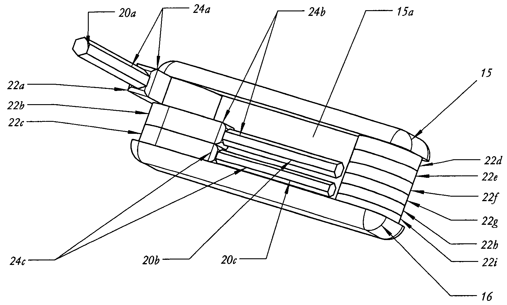
[0043]FIG. 1 is an isometric view of a Folding Hand Toolkit instrument in which embodies elongated lug-tools 24a to 24i are contained within handle side sections 15 and 16. The web sections of the handle 15a and 16a determine the spacing between the handle sides, are integral to the handle and are formed 90 degrees to handle side sections 15 and 16. Elongated lug-tool 24a is an amalgamated assembly of the elongated tool 20a and the lug 22a, as is elongated lug-tool 24b an amalgamated assembly of the elongated tool 20b and the lug 22b and so on with elongated lug-tool 24c through 24i are amalgamated assemblies incorporating elongated tools 20c through 20i with the associated lugs 22c through 22i.

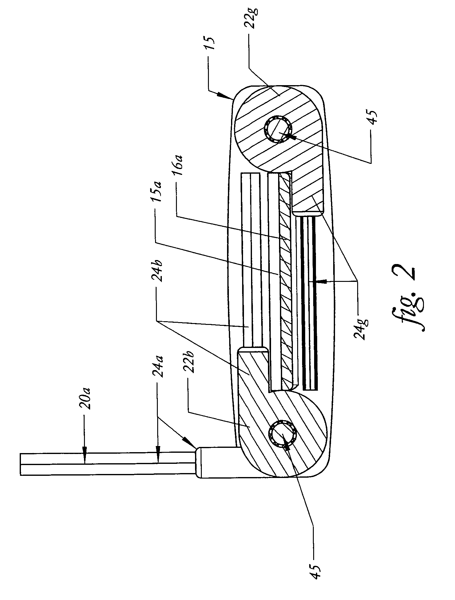
[0044]Elongated lug-tools 24a to 24i are held in place and allowed to rotate by shafts 45 as shown in the cross sectional view of FIG. 2. Elongated lug-tools 24b to 24i are shown in the closed position for storage elongated lug-tools 24a is situated in one of many extended positions for use....


PUM


Abstract

A folding hand tool containing a plurality of elongated tools mounted on a predetermined sized lug and pivotally held in a handle. Shaped complementary sidewalls on the lugs placed adjacent one another provide locking means for positively positioning the plurality of elongated tools in an open or used position. The shaped complementary sidewalls on adjacent lugs may be selectively disengaged with a release or by overcoming a bias of an engaging force. The predetermined sized lugs provide improved transmission of forces and easier manufacture.

Description

FIELD OF THE INVENTION[0001]This invention relates to methods of producing a Folding Handtool Kit instrument that is characterized as a plurality of elongated tools. Each elongated tool having a extended tool working end and a lug based aft end in which any particular tool is selected by pivoting the tool around a shaft that is secured within the confines of a handle and from a retracted closed position for storage within the confines of the handle to an extended open position for use. The extended tool and lug based aft end are produced by separate manufacturing means in order to better employ and broaden flexibility in design especially as it relates to producing a stronger and more secure extended tool and the integration of locking mechanisms with the extended tool.BACKGROUND OF THE INVENTION[0002]Folding Hand Toolkits consisting of elongated tools have long been used by tradesmen and homeowners alike. These toolkits comprise of a plurality of related tools arranged in an assort...

Claims


Application Information

Patent Timeline
IPC IPC(8): B26B3/06B25B11/00B25B23/00B25B23/16B25G1/08F41B13/02F41C27/18
CPCB25B13/56B25B15/008B25F1/04
Inventor JOHNSON, ROBYN MARIE
Owner BASELINE REDEFINED
Learn More