
Vehicle steering and speed control

a technology of speed control and steering system, which is applied in the direction of vehicle components, non-deflectable wheel steering, agriculture tools and machines, etc., can solve the problems of increasing the likelihood of carpal tunnel syndrome, requiring squeezing with the operator's fingers, and the type of steering control is not adjustable for variable hand sizes, so as to reduce the transfer of vibration, reduce the force required, and reduce the effect of vibration transfer

Inactive Publication Date: 2009-01-20
METALCRAFT OF MAYVILLE +1
View PDF37 Cites 42 Cited by
  • Summary
  • Abstract
  • Description
  • Claims
  • Application Information

AI Technical Summary

Benefits of technology

[0014]It is also desired to provide a steering system that reduces or dampens the transfer of vibration from the engine to the steering handle of the mower.
[0015]It is also desired to provide a steering system that reduces the forces required to operate the mower, thereby further reducing the transfer of vibration to the operator's grip.
[0016]It is also desired to provide a mower having a steering system with a steering handle operatively connected to the first and second drives, where rotational movement of the steering handle from a central longitudinal position steers the mower to turn in the direction from a forward direction of travel, and where movement of the steering handle in a vertical direction controls forward propulsion of the mower.

Problems solved by technology

A drawback of this type of steering control mechanism is that it requires squeezing with the operator's fingers to maneuver the mower.
Repeated squeezing motions causes fatigue and increases the likelihood of carpal tunnel syndrome.
Another drawback is that this type of steering control is not adjustable for variable sizes of hands.
The physics of operating larger machinery requires larger steering linkages, which are more difficult to operate with smaller hands.
This further increases fatigue and the likelihood of carpal tunnel syndrome.
Repeated twisting motions with the wrists to control steering of the mower causes fatigue and increases the likelihood of carpal tunnel syndrome.
Another drawback is the difficulty encountered in simultaneously twisting the grip and rotating a grip handle to maneuver a turn of the mower.
In addition, speed limiters for traditional lawnmowers must be operated independently of the steering system, complicating operation and making the lawnmower more difficult to control during a turn.

Method used


Image

  • Vehicle steering and speed control
  • Vehicle steering and speed control
  • Vehicle steering and speed control

Examples


Embodiment Construction

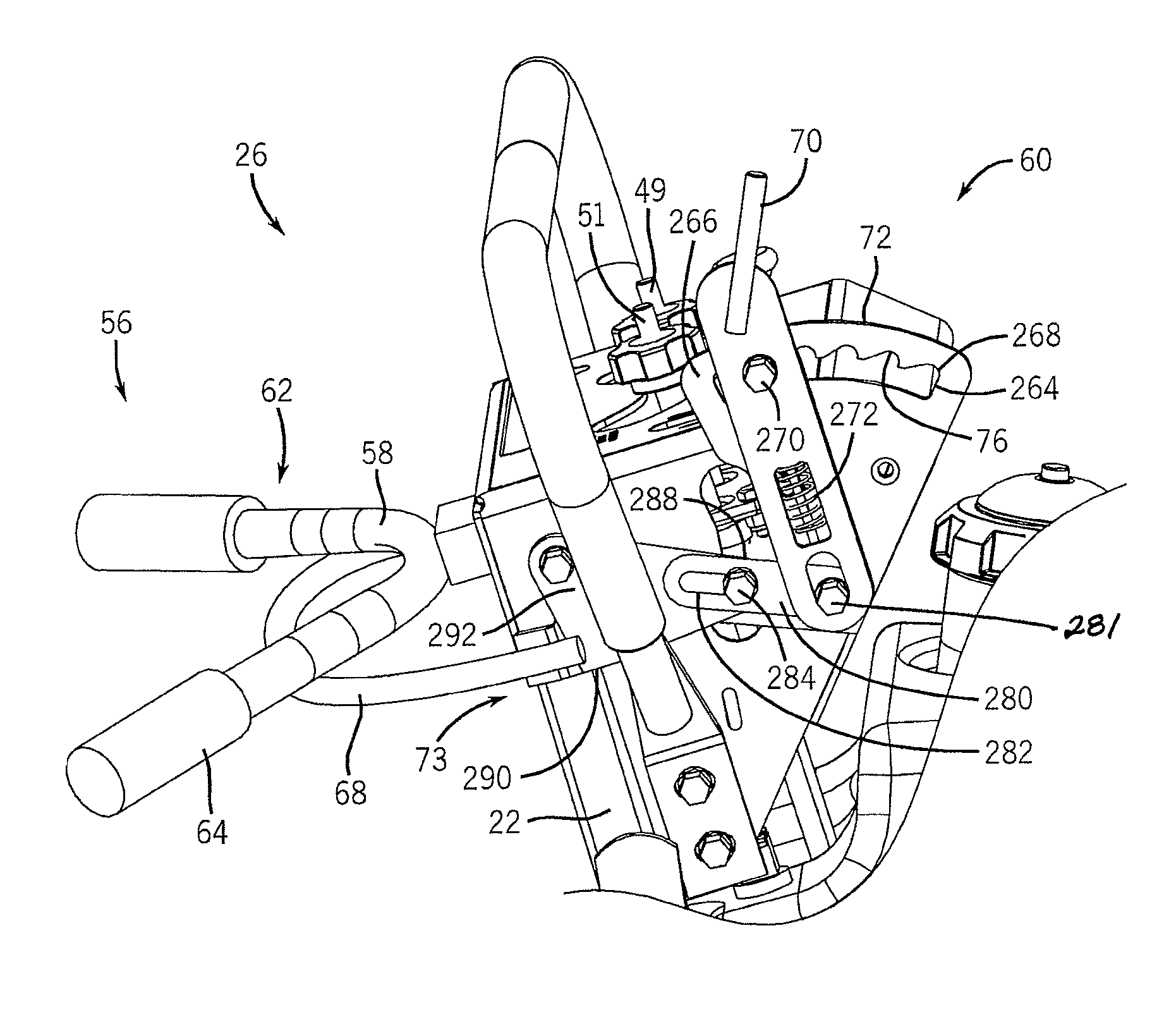
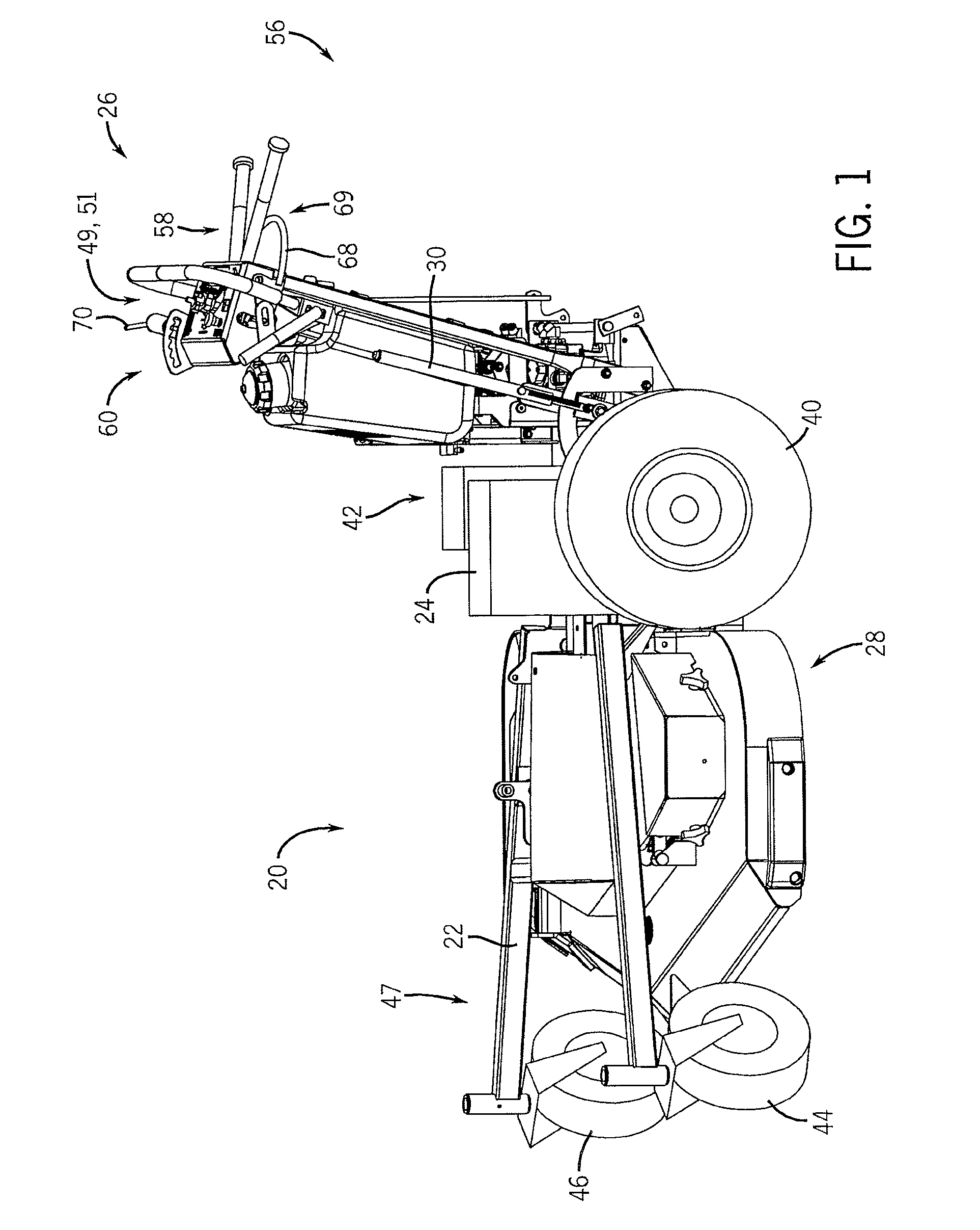
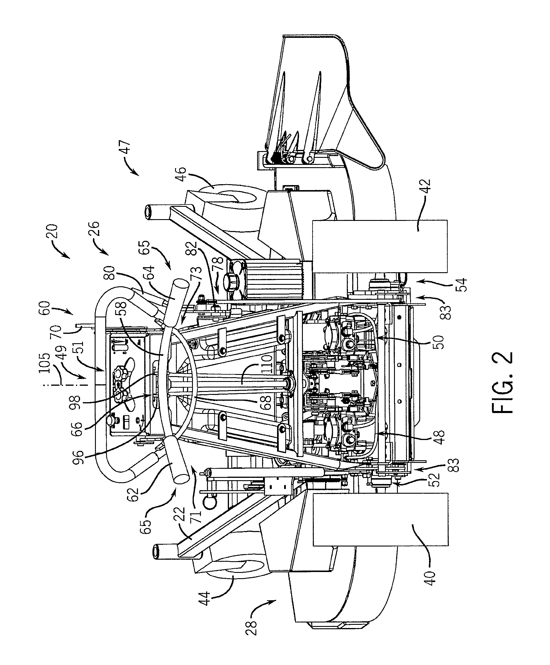
[0036]The drawings illustrate a preferred exemplary embodiment of a preferred embodiment of the invention as incorporated into a walk behind zero turn lawnmower 20. Understandably, one of ordinary skill in the art will appreciate that the control system as disclosed herein is usable with other equipment configurations such stand-on mowers, riding mowers, or other equipment categories such as power buggies, utility carts, or the like. Generally, various configurations of these types of machines are generically defined by the term utility vehicle or a vehicle have more uses that for merely recreational transportation. With respect to the embodiment of a self-propelled zero turn walk behind mower illustrated in the accompanying drawings, it will be appreciated that like reference numerals represent like parts throughout the drawings.

[0037]Referring to FIGS. 1-3, walk-behind, self-propelled lawnmower 20 includes a frame 22 having an engine 24, a control system 26, and a mower deck 28 su...


PUM


Abstract

A control system for a lawnmower includes a handlebar connected to the lawmnower for controlling direction and speed of travel of the lawmower based on a position of the handlebar relative to the lawnmower. The control system is connected to a drive system of the lawnmower such that changing the elevation of the handlebar adjusts operation of a number of wheel drive units and turning of the handlebar relative to the lawnmower adjusts operation of one wheel drive unit relative to another wheel drive unit.

Description

CROSS-REFERENCE TO RELATED APPLICATIONS[0001]This application claims priority to Provisional Application Ser. No. 60 / 743,610 filed on Mar. 21, 2006, titled “Steering System For A Lawnmower” and the disclosure of which is incorporated herein.BACKGROUND OF THE INVENTION[0002]1. Field of the Invention[0003]The invention relates to a steering system and, more particularly, relates to a steering system for a self-propelled lawnmower.[0004]2. Discussion of the Related Art[0005]Lawnmowers equipped with dual hydraulically-powered drive systems that propel the drive wheels on each side of the mower are known in the grooming a lawns. Turning is achieved by driving each drive wheel at different speeds. They can even be turned in different directions for a very sharp or even a “zero-turn” radius, where the mower pivots about the midpoint drive wheel axis. This kind of drive wheel steering system is more maneuverable than traditional vehicle steering systems that employ one set of wheels, either...

Claims


Application Information

Patent Timeline
Patent Type & Authority Patents(United States)
IPC IPC(8): B62D51/04
CPCA01D34/67A01D34/824B62D11/006B62D51/001B62D51/04
Inventor SUGDEN, DAVID J.HALL, JAMES W.
Owner METALCRAFT OF MAYVILLE
Learn More