Heat sink clip and assembly

a technology of heat sink and assembly, which is applied in the direction of cooling/ventilation/heating modifications, semiconductor/solid-state device details, semiconductor devices, etc., can solve the problems of difficult operation of heat sink clips, difficult for operators to mount locking feet, and a lot of force on pressing the operation handle into position

Inactive Publication Date: 2009-01-20
HON HAI PRECISION IND CO LTD +1
View PDF13 Cites 12 Cited by
  • Summary
  • Abstract
  • Description
  • Claims
  • Application Information

AI Technical Summary

Problems solved by technology

However, it is difficult to operate the heat sink clip.
Pressing the operation handle into position requires a lot of force, and it is not easy for the operator to mount the locking foot onto the retention module.

Method used


Image

  • Heat sink clip and assembly
  • Heat sink clip and assembly
  • Heat sink clip and assembly

Examples


Embodiment Construction

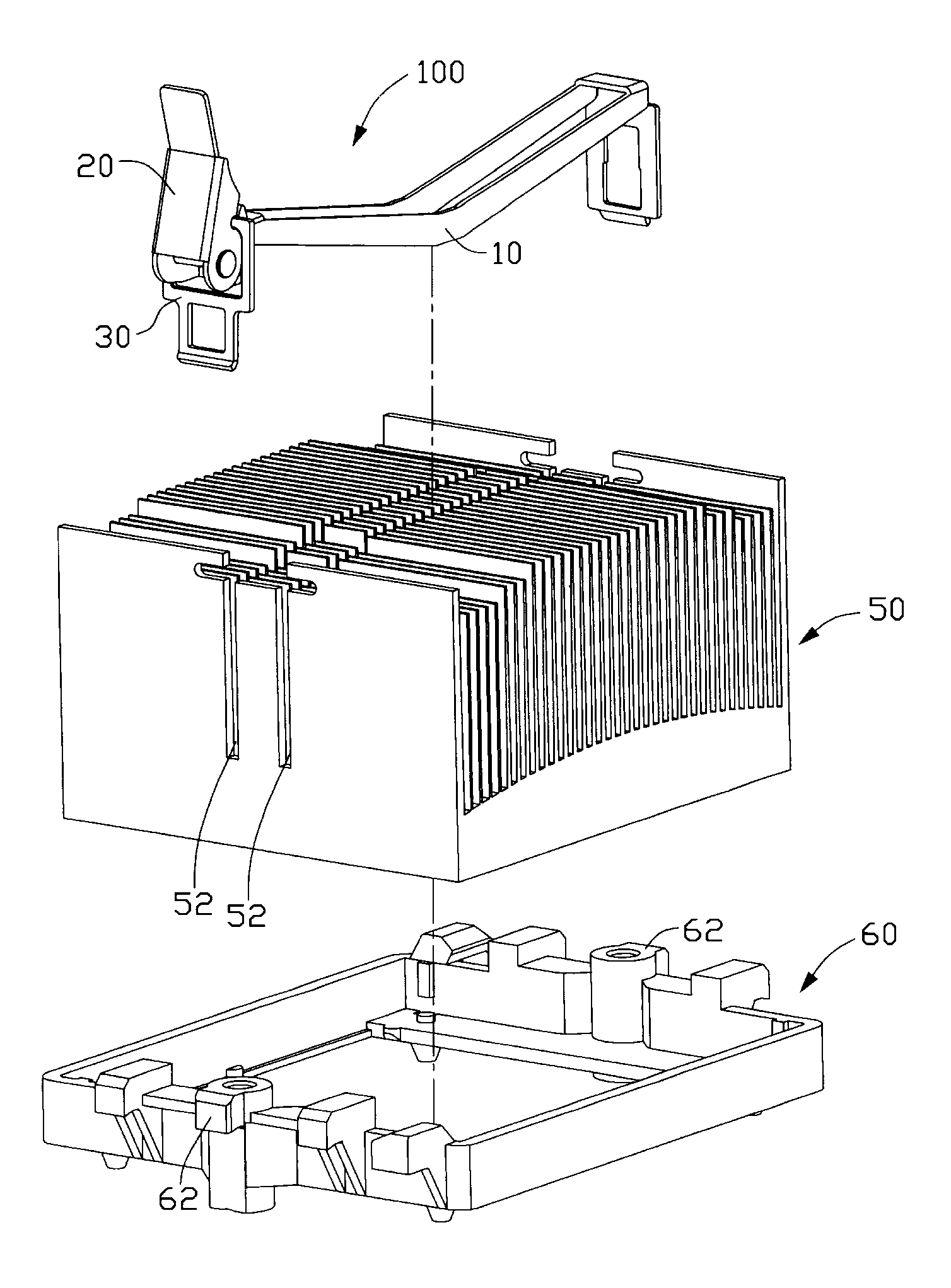
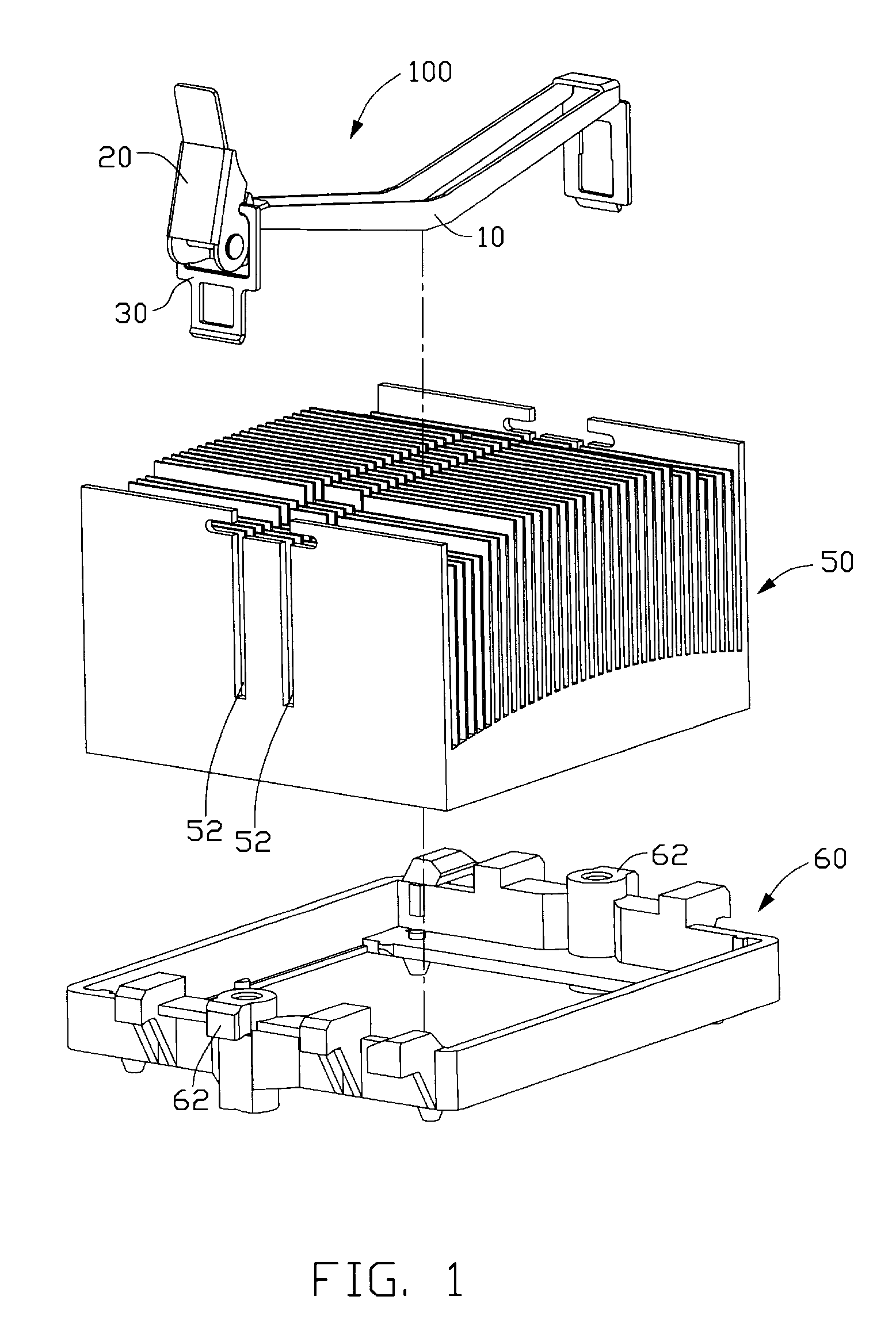
[0013]Referring to FIG. 1, a heat sink assembly in accordance with a preferred embodiment of the present invention comprises a heat sink clip 100, a heat sink 50 and a retention module 60. The heat sink clip 100 cooperates with the retention module 60 to secure the heat sink 50. The heat sink 50 defines two parallel locating grooves 52 for receiving the heat sink clip 100 therein. Each of two opposite sides of the retention module 60 forms a locking block 62 extending outwardly therefrom.

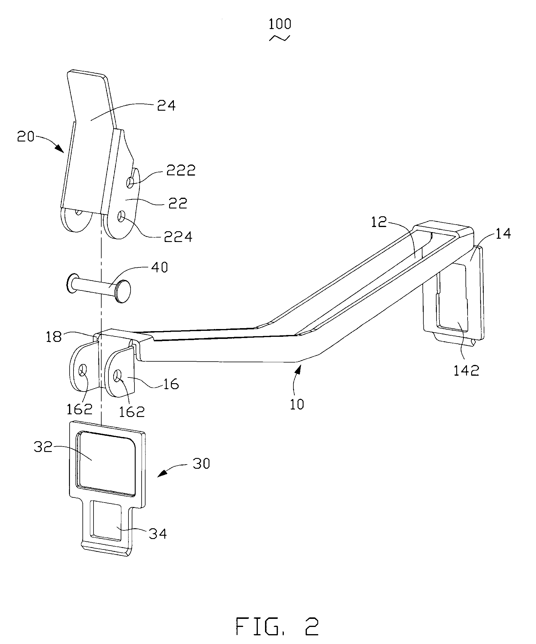
[0014]Referring to FIG. 2, the heat sink clip 100 comprises a body 10, an actuating member 20, a movable fastener 30 and a pivot 40.

[0015]The body 10 defines an elongated slot 12 between one end and the other end thereof. The body 10 has a locking arm 14 integrally formed at one end thereof, the locking arm 14 defines a mounting hole 142 for engaging with the locking block 62 at one side of the retention module 60. The body 10 forms a securing portion 16 and a bearing portion 18 at the other end the...


PUM


Abstract

A heat sink clip and an assembly incorporating such clip are provided. The heat sink clip comprises: a body, an actuating member and a movable fastener. The body has a securing portion formed at one end thereof. The actuating member is pivotably mounted to the securing portion of said body and has a main body. The main body defines an open aperture therein. The movable fastener is pivotably connected to the open aperture of the actuating member. The actuating member is turnable relative to the body between an unlocked position and a locked position.

Description

FIELD OF THE INVENTION[0001]The present invention relates to a heat sink assembly, and particularly to a heat sink assembly incorporating a clip which can conveniently mount the heat sink assembly to a heat generating unit.DESCRIPTION OF RELATED ART[0002]With the continuing advance of computer technology, electronic components such as computer central processing units (CPUs) are being made to operate at higher operational speeds and with greater functional capabilities. When a CPU operates at a high speed in a computer enclosure, its temperature increases greatly. To avoid damage, the heat generated by the CPU must be dissipated quickly, for example, by using a heat sink attached to the surface of the CPU in the enclosure. This allows the CPU and other high-performance electronic components in the enclosure to function within their normal operating temperature ranges, thereby assuring the quality of CPU data management, storage and transfer. Usually, a clip is required for mounting ...

Claims


Application Information

Patent Timeline
Patent Type & Authority Patents(United States)
IPC IPC(8): H05K7/20
CPCH01L23/4093H01L2924/0002H01L2924/00
Inventor YANG, CHENG-PENG
Owner HON HAI PRECISION IND CO LTD
Why Eureka
Try Eureka