
Corrugated fin and frame assembly for battery cooling

Active Publication Date: 2011-12-01
GM GLOBAL TECH OPERATIONS LLC
View PDF10 Cites 150 Cited by
  • Summary
  • Abstract
  • Description
  • Claims
  • Application Information

AI Technical Summary

Benefits of technology

[0010]In another embodiment, a battery pack assembly, comprises a plurality of cooling modules disposed in a stack, each of the cooling modules including a frame and a cooling fin coupled to the frame, the frame having a plurality of legs forming an opening through a central portion of the frame, at least one of the plurality of legs including a slot formed therethrough, the cooling fin having a corrugated plate interposed between a first plate and a second plate forming a plurality of fluid flow channels between the first plate and the second plate, the flow channels in heat transfer communication with at least one of the corrugated plate, the first plate, and the second plate; at least one battery cell disposed between adjacent cooling modules and in heat transfer communication with the cooling fin of one of the cooling modules, wherein the cooling fin facilitates a transfer of heat energy between the battery cell and the flow channels formed in the cooling fin; an end plate disposed on at least one end of the battery pack assembly; and a tension member providing a compressive force on the stack of the cooling modules, the battery cells, and the end plate.

Problems solved by technology

When overheated or otherwise exposed to high-temperature environments, the heat can impact the operation of the lithium-ion battery cells.
To provide such cooling systems and compressible components, a complexity of the battery pack assembly is undesirably increased.
Accordingly, a cost of the battery pack assembly is undesirably increased.

Method used


Image

  • Corrugated fin and frame assembly for battery cooling
  • Corrugated fin and frame assembly for battery cooling
  • Corrugated fin and frame assembly for battery cooling

Examples


Embodiment Construction

[0024]The following detailed description and appended drawings describe and illustrate various embodiments of the invention. The description and drawings serve to enable one skilled in the art to make and use the invention, and are not intended to limit the scope of the invention in any manner.

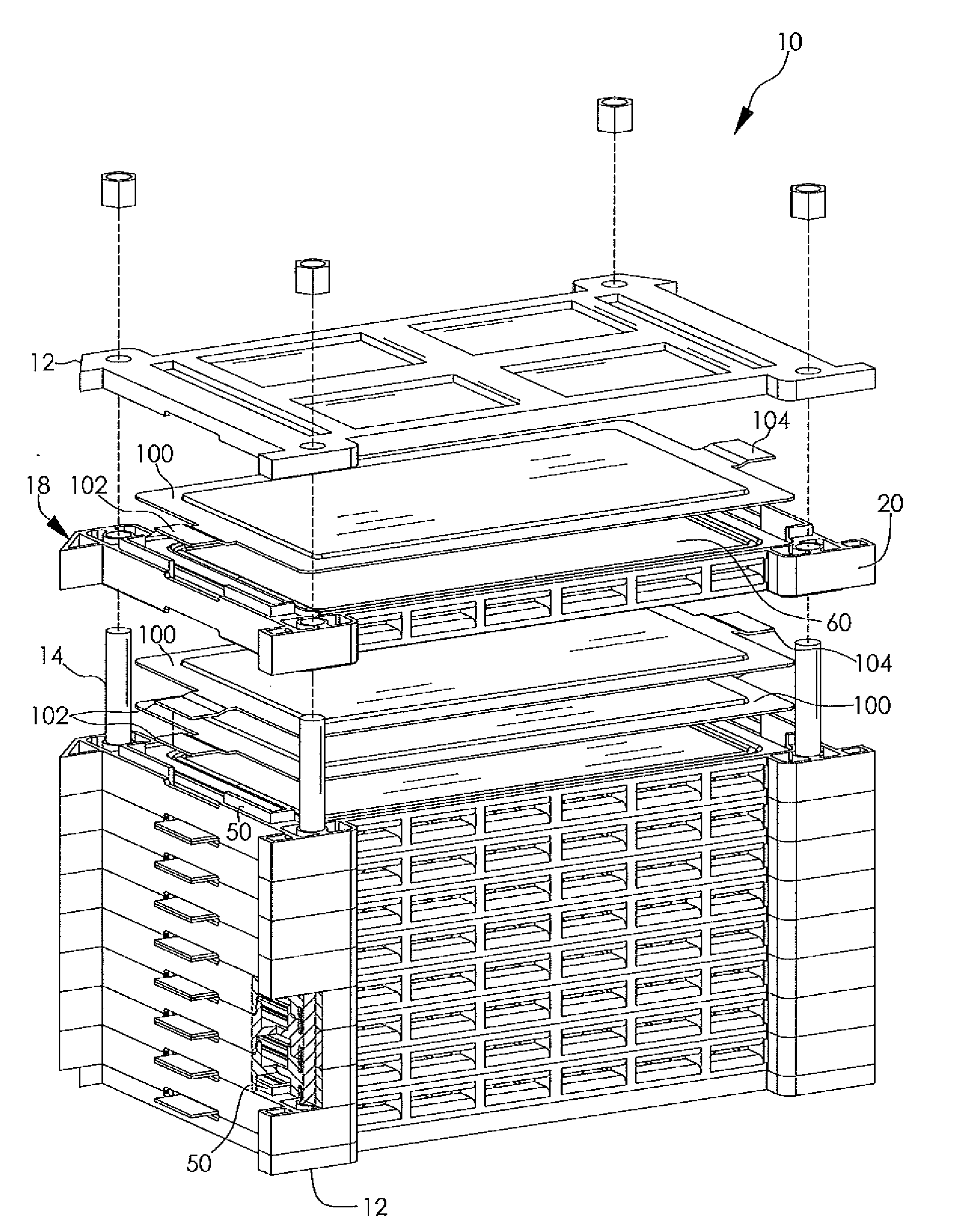
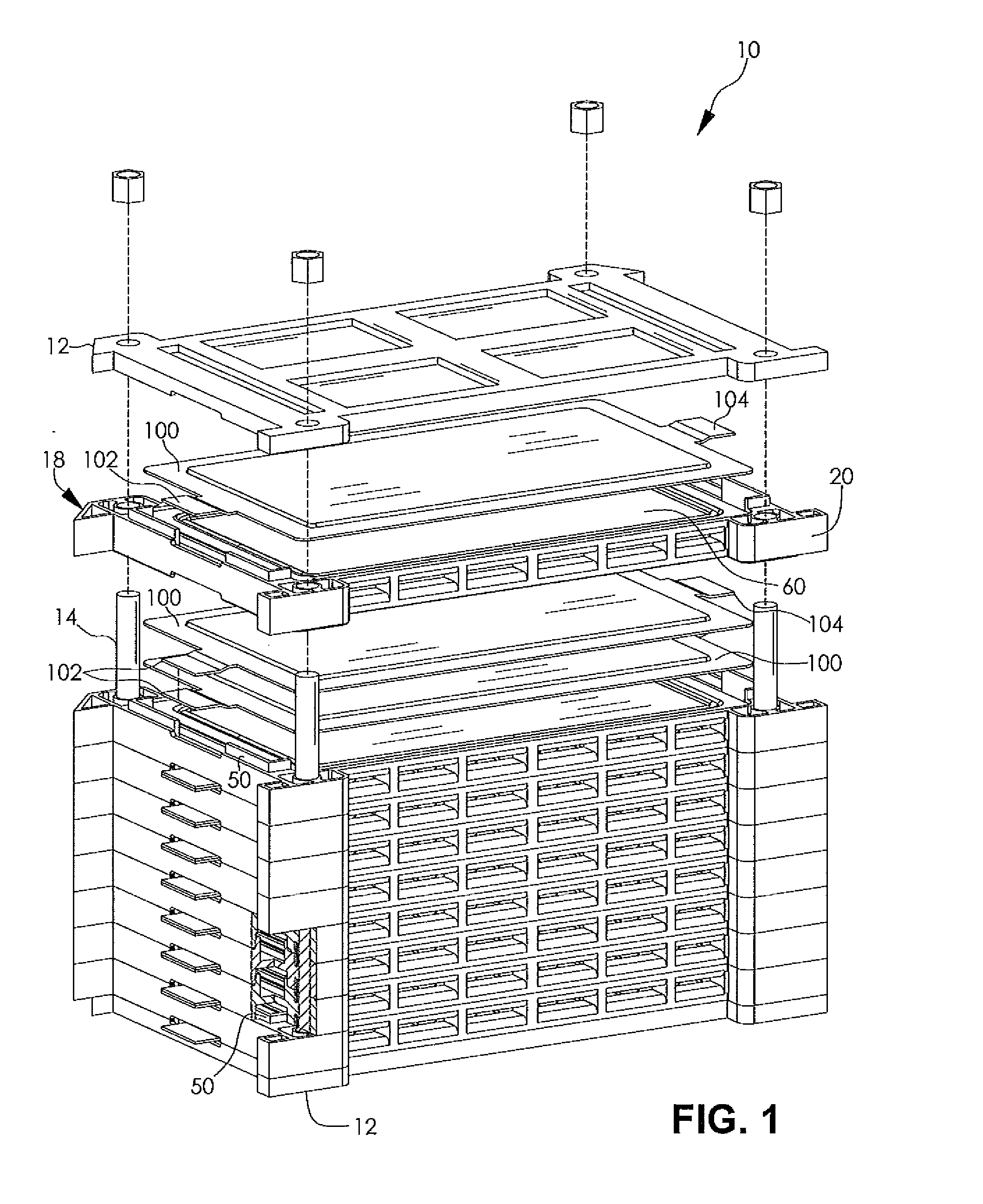
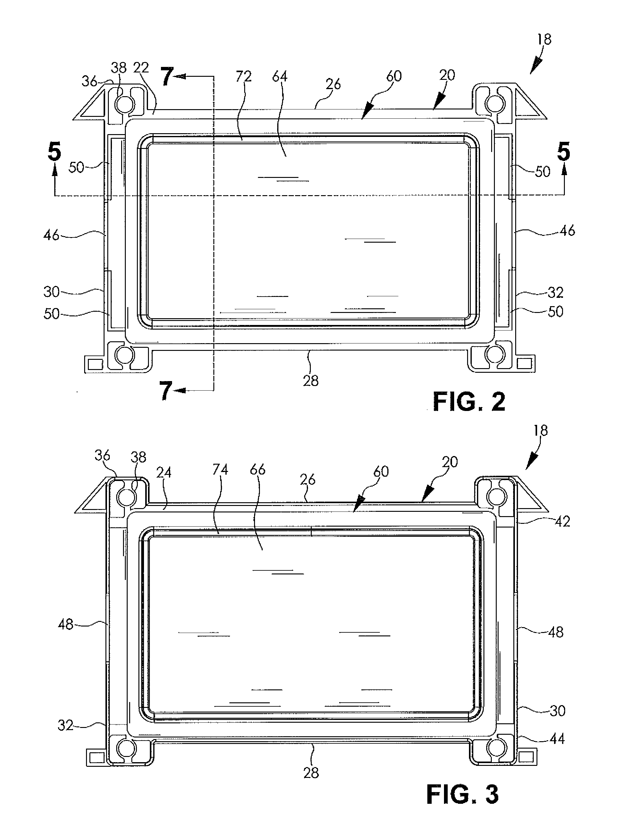
[0025]FIG. 1 shows a battery pack assembly 10 according to an embodiment of the present disclosure for supplying electric power to an associated electric device such as an electric vehicle, for example. The battery pack assembly 10 includes a plurality of cooling modules 18 having a cooling fin 60 coupled to a frame 20. The cooling modules 18 are arranged in a stacked relation having a pair of battery cells 100 disposed therebetween. An end plate 12 may be provided on one or both ends of the battery pack assembly 10, In the illustrated embodiment, the battery cell 100 is a prismatic lithium-ion battery cell having a first electrically conductive tab 102 and a second electrically conductive tab...


PUM


Abstract

A cooling module for a battery pack assembly is disclosed. The cooling module includes a frame having a plurality of legs forming an opening through a central portion of the frame, at least one of the plurality of legs including a slot formed therethrough. A cooling fin is coupled to the frame. The cooling fin includes a corrugated plate interposed between a first plate and a second plate forming a plurality of fluid flow channels between the first plate and the second plate. The cooling modules are disposed in a stack having at least one battery cell disposed between adjacent cooling modules. The battery cell is in heat transfer communication with the cooling fin of at least one cooling module, wherein the cooling fin facilitates a transfer of heat energy between the battery cell and the flow channels formed in the cooling fin.

Description

FIELD OF THE INVENTION[0001]The present disclosure relates to a battery pack and more particularly to a cooling fin and frame assembly for a battery pack.BACKGROUND OF THE INVENTION[0002]A battery cell has been proposed as a clean, efficient and environmentally responsible power source for an electric device such as an electric vehicle, for example. One type of battery cell is a lithium-ion battery cell. Typically, a plurality of individual lithium-ion battery cells is provided in a stacked configuration to supply an amount of electric power sufficient to operate the electric device.[0003]The lithium-ion battery cells are known to generate heat during a charging and a discharging thereof. When overheated or otherwise exposed to high-temperature environments, the heat can impact the operation of the lithium-ion battery cells. Cooling systems are typically employed with the lithium-ion battery cells, as well as other types of battery cells, to militate against undesirable overheating ...

Claims


Application Information

Patent Timeline
IPC IPC(8): H01M10/50
CPCH01M10/0525H01M10/5004Y02T10/7011H01M10/5059H01M10/5046H01M10/613H01M10/6551H01M10/6557Y02E60/10Y02T10/70
Inventor MARTZ, WILLIAM L.DUFFIELD, MICHAELQUICK, MEGAN J.BARTER, STUART D.SKALA, GLENN W.FOGARASSY, STEVEN J.CONNOR, ERIC J.GREY, THADDEUS J.
Owner GM GLOBAL TECH OPERATIONS LLC
Learn More