
Storage system and method for saving energy based on storage classes with corresponding power saving policies

Inactive Publication Date: 2008-12-30
IBM CORP
View PDF16 Cites 25 Cited by
  • Summary
  • Abstract
  • Description
  • Claims
  • Application Information

AI Technical Summary

Benefits of technology

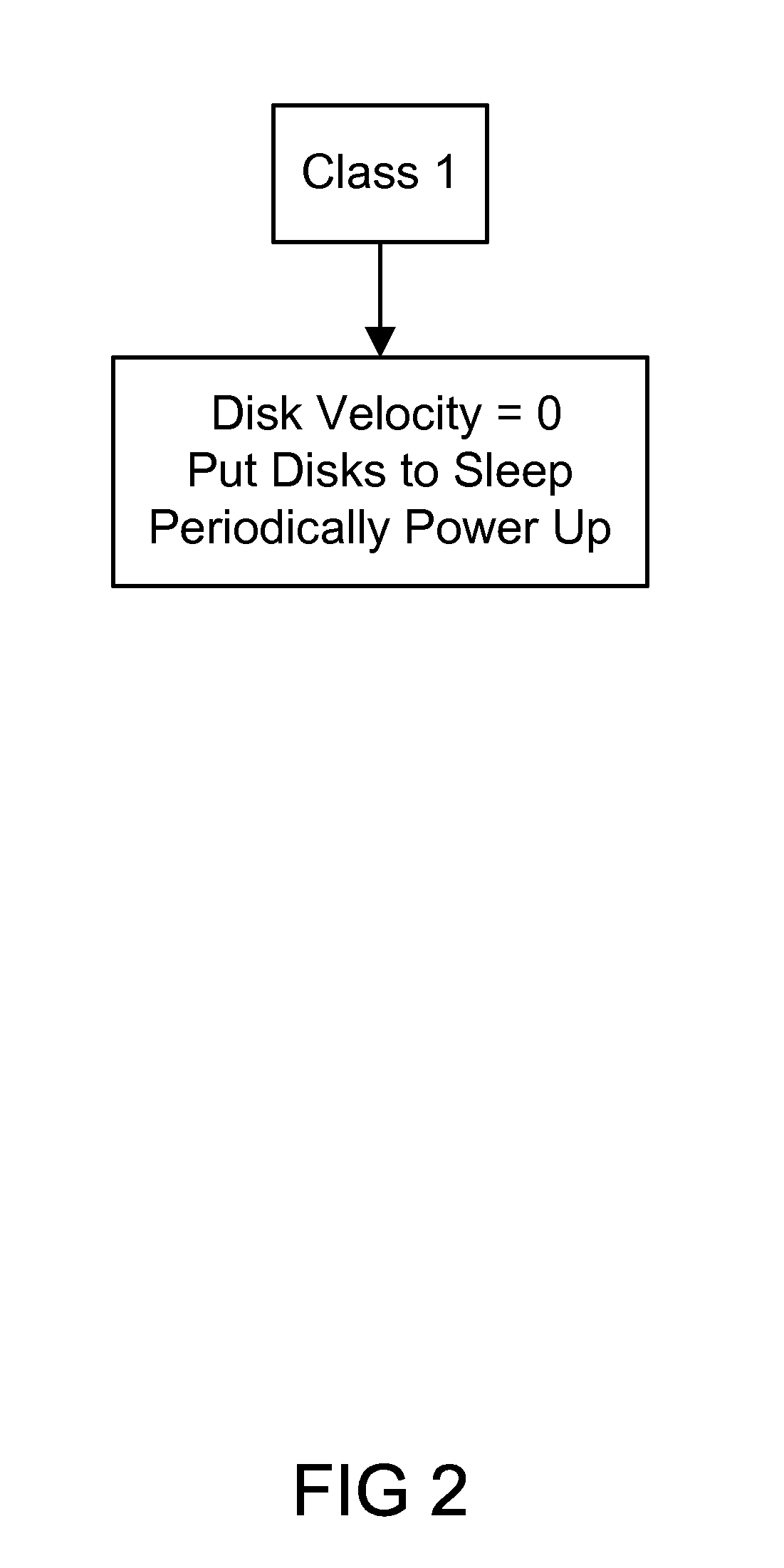
[0004]The invention implements Power On Demand, where a sort of sleep (i.e., reduced power) mode is enabled for every individual component of a storage subsystem, thereby minimizing overall consumption for the full subsystem and making it flexibly adapting to changing I / O loads. The invention provides a method to spin down the disk drives belonging to groups that are not used for a long time. For instance, RAID arrays without volumes don't need to have spinning drives at all the time, until volumes are actually created. Or, RAID ranks without license key (whose capacity can be increased on demand) do not have to be continuously under full power. Additional types of drives can be found which can selectively be powered down for a longer time without doing any harm to the performance of the storage subsystem. Although powering on represents some loss of time, if powering on is only needed after a long duration (maybe a month) when the first volume is created, this small performance lag may be acceptable given the enormous amount of energy saved in the mean time. Such systems are not currently available, and the current technologies on the market simply set power on for all the drives or fans.
[0007]When power can be saved with disk drives in a disk system then there are also potentials to save power consumed by power supplies. Because power supply controls the fan speed based upon the power consumption of the disk drives. If the disks save power then ultimately the power supplies can slow the fan down.

Problems solved by technology

Such systems are not currently available, and the current technologies on the market simply set power on for all the drives or fans.
If the disks save power then ultimately the power supplies can slow the fan down.

Method used


Image

  • Storage system and method for saving energy based on storage classes with corresponding power saving policies
  • Storage system and method for saving energy based on storage classes with corresponding power saving policies
  • Storage system and method for saving energy based on storage classes with corresponding power saving policies

Examples


Embodiment Construction

[0010]In general, all components of the storage subsystem should use power management or a reduced-power mode. After hours of non-usage, an individual component should go into a lower-power mode. In particular for the disk drives, the invention teaches a method to automatically power down drives using an internal power-management within each drive and to identify certain groups of drives which will not be in use for long time, and to set these drives to even lower power levels.

[0011]An embodiment of invention powers off for all drives which are not part of fully formatted RAID arrays, or (as in DS8000®) belonging to arrays which are not part of an “Extent Pool”, i.e. where no volumes can currently be created on. When a request comes to format an array, to bring it into an Extent Pool, or to create a volume on it: The time lag for this to power these drives on then will be acceptable. In particular, this turns off disk drives for all RAID ranks whose capacity can be increased on dema...


PUM


Abstract

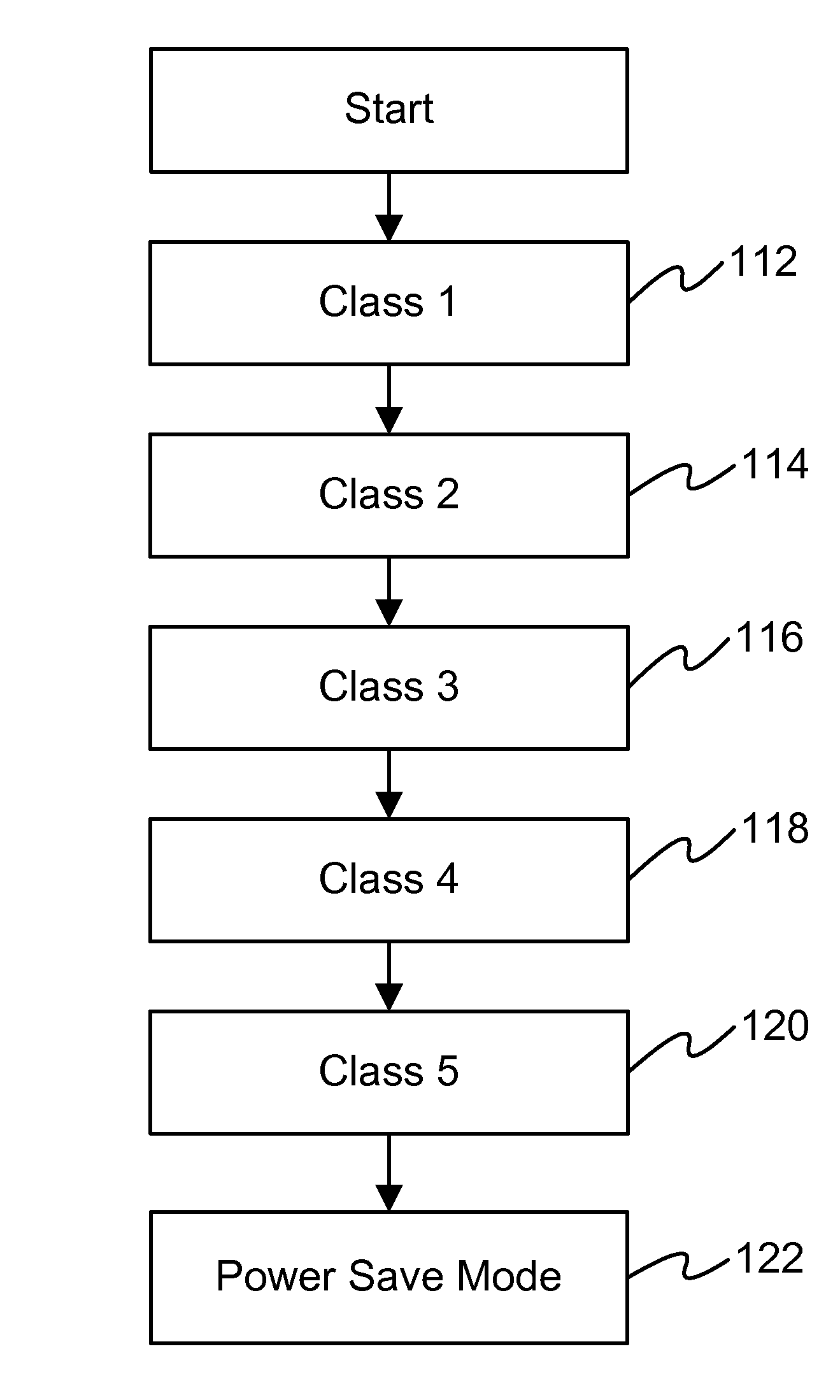
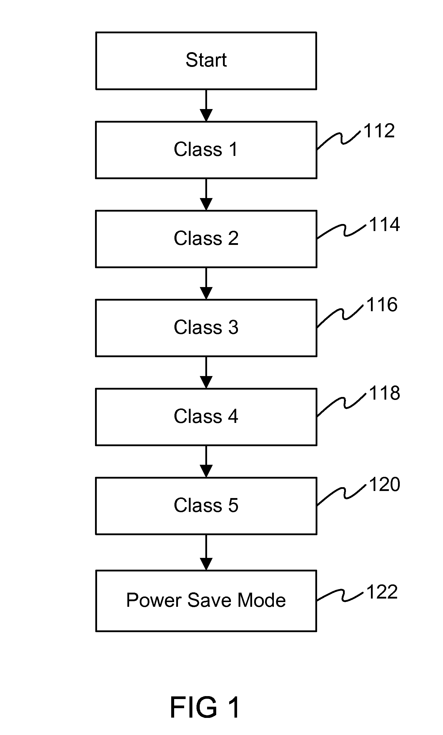
An example of the invention classifies disks drives based on their purpose and associating power-saving policies in multiple classes. The system implements Power On Demand, where a reduced power mode is enabled for every individual component of a storage subsystem. In addition, an embodiment of this invention extends a few power modes used in the prior art and allows almost infinite number of power modes when instructing a disk drive (via its I / O interface such as a SCSI or fiber channel interface) to enter a certain power saving mode. Furthermore, an embodiment of invention teaches a system and methods to save power in a disk system comprising a plurality of disk controllers and a plurality of disk drives, arranged in a plurality of arrays, where each array includes several (e.g., 4-16) disk drives.

Description

BACKGROUND OF THE INVENTION[0001]Unlike servers with power-down modes (e.g., sleep mode, hibernation mode) such energy-saving modes are not currently used for storage subsystems. The typical storage subsystem powers on all disk drives for all the time, even those drives which are practically never used. Spinning drives is quite costly in terms of energy consumption, hence lots of cooling is needed. There have been initiatives targeting data centers as well as individual machines for lowering power consumption, cooling effort, and carbon footprint, as the market for “green” initiatives in IT is growing with high customer interest.[0002]In a disk system according to prior art such as IBM® DS8000®, IBM® DS6000® and IBM® DS4000® comprise a plurality of disk drives and disk controllers. Disk drives are arranged in arrays (such as RAID-5, RAID-10, RAID-6) to improve the availability. One array usually comprises 4-16 disks. The arrays in such disk systems have different purposes: some are ...

Claims


Application Information

Patent Timeline
IPC IPC(8): G06F1/32
CPCG06F1/3203G06F1/325G06F1/3268Y02B60/1246Y02B60/32Y02D10/00Y02D30/50
Inventor KIMMEL, PETERGARDELEGEN, THOMASHAUSTEIN, NILSWINARSKI, DANIEL JAMES
Owner IBM CORP
Learn More