
Molten metal pump components

a technology of molten metal pumps and components, which is applied in the direction of piston pumps, positive displacement liquid engines, manufacturing converters, etc., can solve the problems of rotor shaft breakage and weak points that may break

Inactive Publication Date: 2008-12-30
MOLTEN METAL EQUIP INNOVIATIONS LLC
View PDF347 Cites 92 Cited by
  • Summary
  • Abstract
  • Description
  • Claims
  • Application Information

AI Technical Summary

Benefits of technology

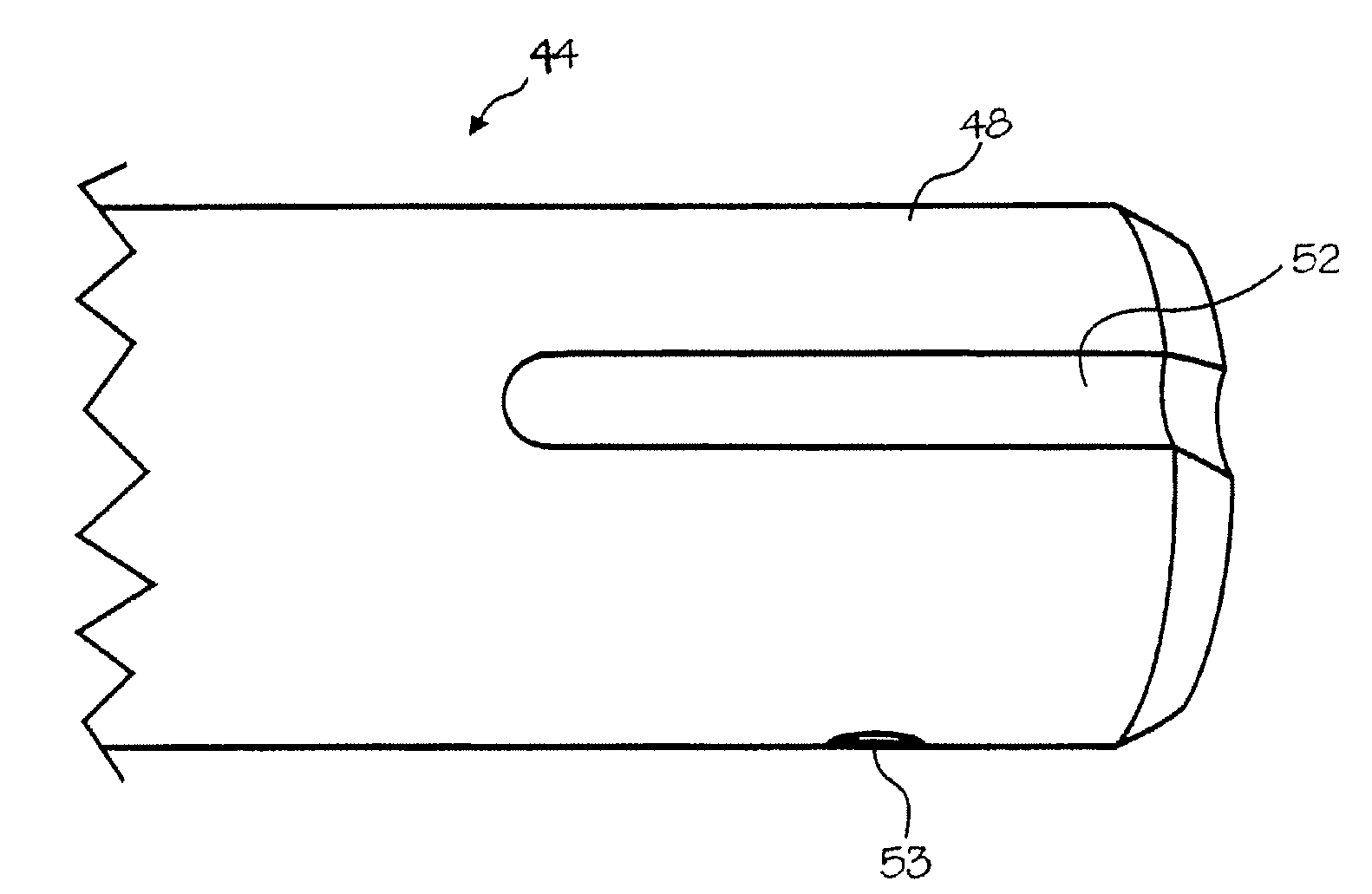
"The present invention provides improved rotor shafts and a coupling and rotor that can be used with these shafts. The rotor shafts have a first end with a keyway and a cavity of a coupling that includes a projection that applies driving force to the rotor shaft. Another rotor shaft has flat, shallow threads instead of pointed threads. The rotor shafts may have both a first end and a second end or shallow, flat threads for use with a coupling having shallow, flat threads. The invention also includes pumps that use these improved components."

Problems solved by technology

A problem with known molten metal pumps is that machining the graphite components, such as the rotor and rotor shaft, can create weak points that may break during operation.
The threads formed in the end of the rotor shaft are typically pointed and create weak areas that can cause the rotor shaft to break during operation.
Removing this material from the end of the rotor shaft also weakens the shaft and can cause breakage.

Method used


Image

  • Molten metal pump components
  • Molten metal pump components
  • Molten metal pump components

Examples


Embodiment Construction

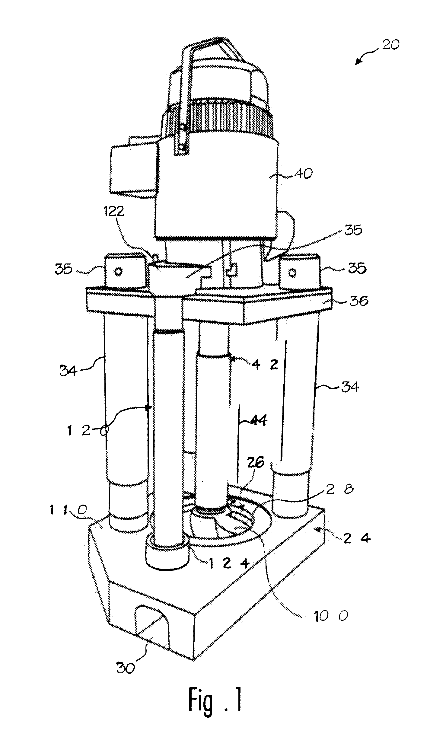
[0030]Referring now to the drawing where the purpose is to illustrate and describe different embodiments of the invention, and not to limit same, FIG. 1 shows a molten metal pump. During operation, Pump 20 is usually positioned in a molten metal bath B in a pump well, which is normally part of the open well of a reverbatory furnace.

[0031]The components of pump 20 that are exposed to the molten metal are preferably formed of structural refractory materials, which are resistant to degradation in the molten metal. Carbonaceous refractory materials, such as carbon of a dense or structural type, including graphite, graphitized carbon, clay-bonded graphite, carbon-bonded graphite, or the like have all been found to be most suitable because of cost and ease of machining. Such components may be made by mixing ground graphite with a fine clay binder, forming the non-coated component and baking, and may be glazed or unglazed. In addition, components made of carbonaceous refractory materials m...


PUM

PropertyMeasurementUnit
lengthaaaaaaaaaa
widthaaaaaaaaaa
depthaaaaaaaaaa

Abstract

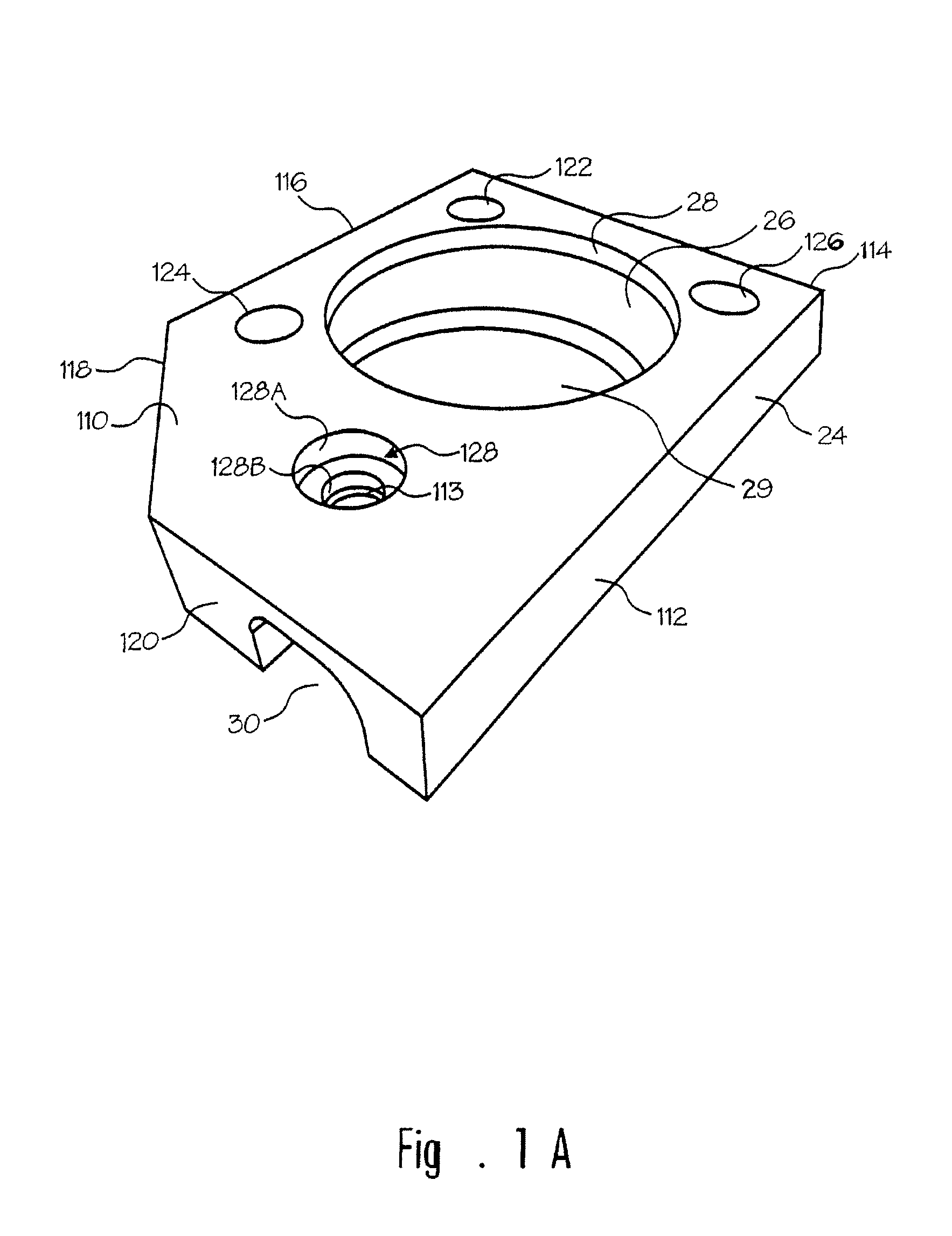
Improved components for a molten metal pump include a coupling for connecting a rotor shaft to a motor shaft, a rotor shaft and a rotor. The rotor shaft has a first end and a second end wherein the first end optionally has a vertical keyway formed in the outer surface of the shaft. The second end optionally has flat, shallow threads. The coupling can be one-piece or multi-piece, includes a cavity for receiving the first end of the rotor shaft and, if the first end of the rotor shaft has a keyway, the coupling includes a projection in the cavity for being received at least partially in the keyway. The rotor includes a connective portion that connects to the second end of the rotor shaft. If the second end of the rotor shaft includes flat, shallow threads, the connective portion is essentially a bore having flat, shallow threads configured to receive the second end of the rotor shaft. Optionally, the first end of the rotor shaft may have flat, shallow threads in which case the coupling would have a cavity that receives the first end of the rotor shaft, wherein the cavity has flat, shallow threads.

Description

CROSS-REFERENCE TO RELATED APPLICATIONS[0001]This application is a continuation of, and claims priority under 35 U.S.C. §§ 119 and 120 to, U.S. patent application Ser. No. 10 / 619,405, filed on Jul. 14, 2003 still pending, by Paul V. Cooper, and U.S. patent application Ser. No. 10 / 620,318, filed on Jul. 14, 2003 still pending, by Paul V. Cooper.FIELD OF THE INVENTION[0002]The invention relates to components used in molten metal pumps, particularly a rotor shaft, a rotor shaft coupling and a connective portion on a rotor to connect to a rotor shaft. The components are designed to facilitate connections while alleviating breakage of the components.BACKGROUND OF THE INVENTION[0003]As used herein, the term “molten metal” means any metal or combination of metals in liquid form, such as aluminum, copper, iron, zinc and alloys thereof. The term “gas” means any gas or combination of gases, including argon, nitrogen, chlorine, fluorine, freon, and helium, which are released into molten metal....

Claims


Application Information

Patent Timeline
Patent Type & Authority Patents(United States)
IPC IPC(8): F04B17/00F04D7/06F04D13/02F04D29/02
CPCF04D15/0044F04D29/2227F04D29/026F04D7/00F04D13/021F04D7/065F04D29/2216F04D29/4213Y10T428/12F05D2300/171F05D2300/20F05D2300/224F04D29/044F04D29/20
Inventor COOPER, PAUL V.
Owner MOLTEN METAL EQUIP INNOVIATIONS LLC
Learn More