
Random walk filter timing recovery loop

a random walk filter and timing recovery technology, applied in the field of digital communication, can solve the problems of poor data detection, conventional timing recovery loops disadvantageously experience long hang up time, random walk filters have not been adapted to improve the bit clock locking stability of timing recovery loops, etc., to improve the detection of binary data streams encoded

Active Publication Date: 2008-12-23
THE AEROSPACE CORPORATION
View PDF9 Cites 3 Cited by
  • Summary
  • Abstract
  • Description
  • Claims
  • Application Information

AI Technical Summary

Benefits of technology

[0006]An object of the invention is to provide improved detection of a binary data stream encoded in a baseband signal.
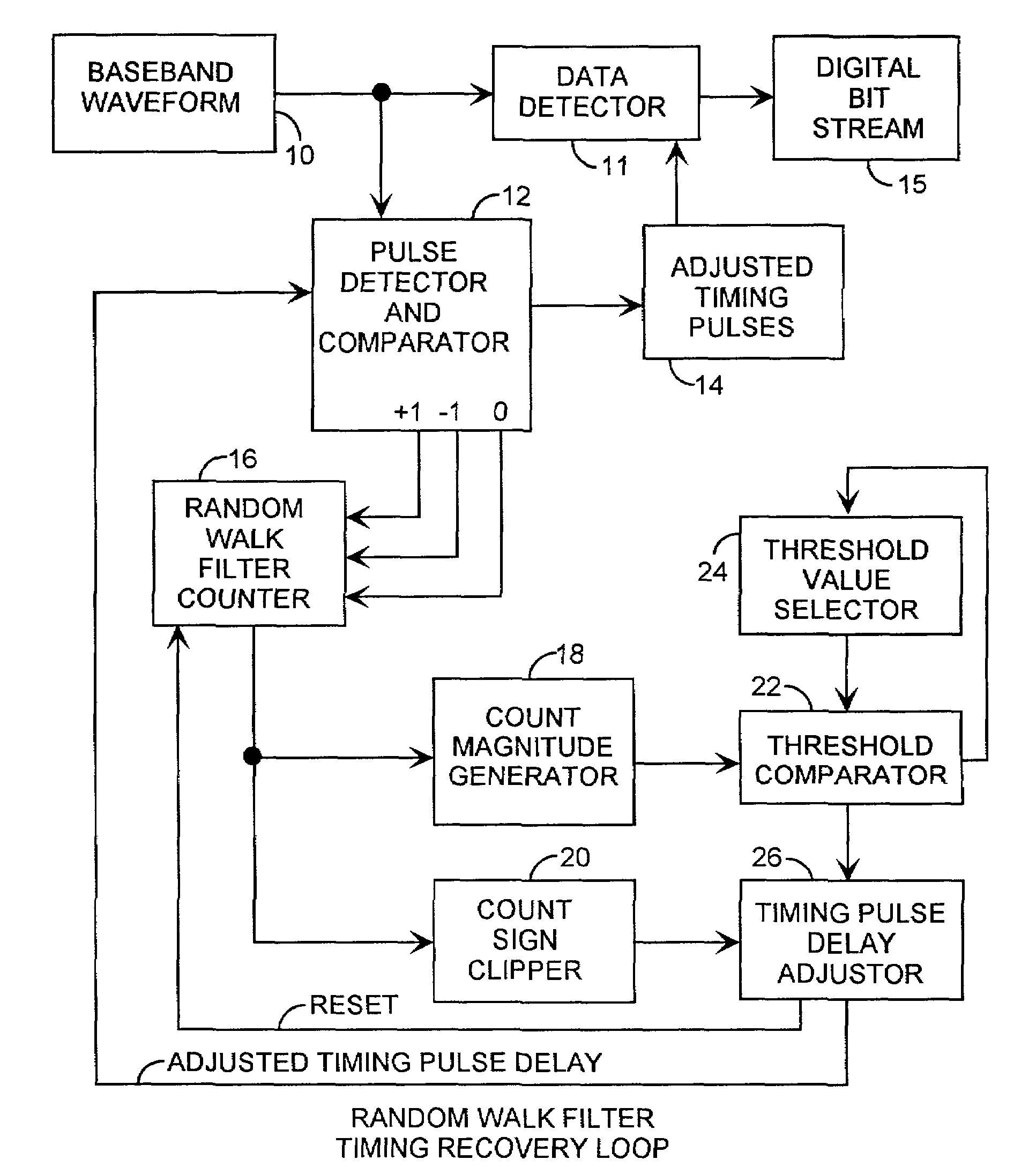
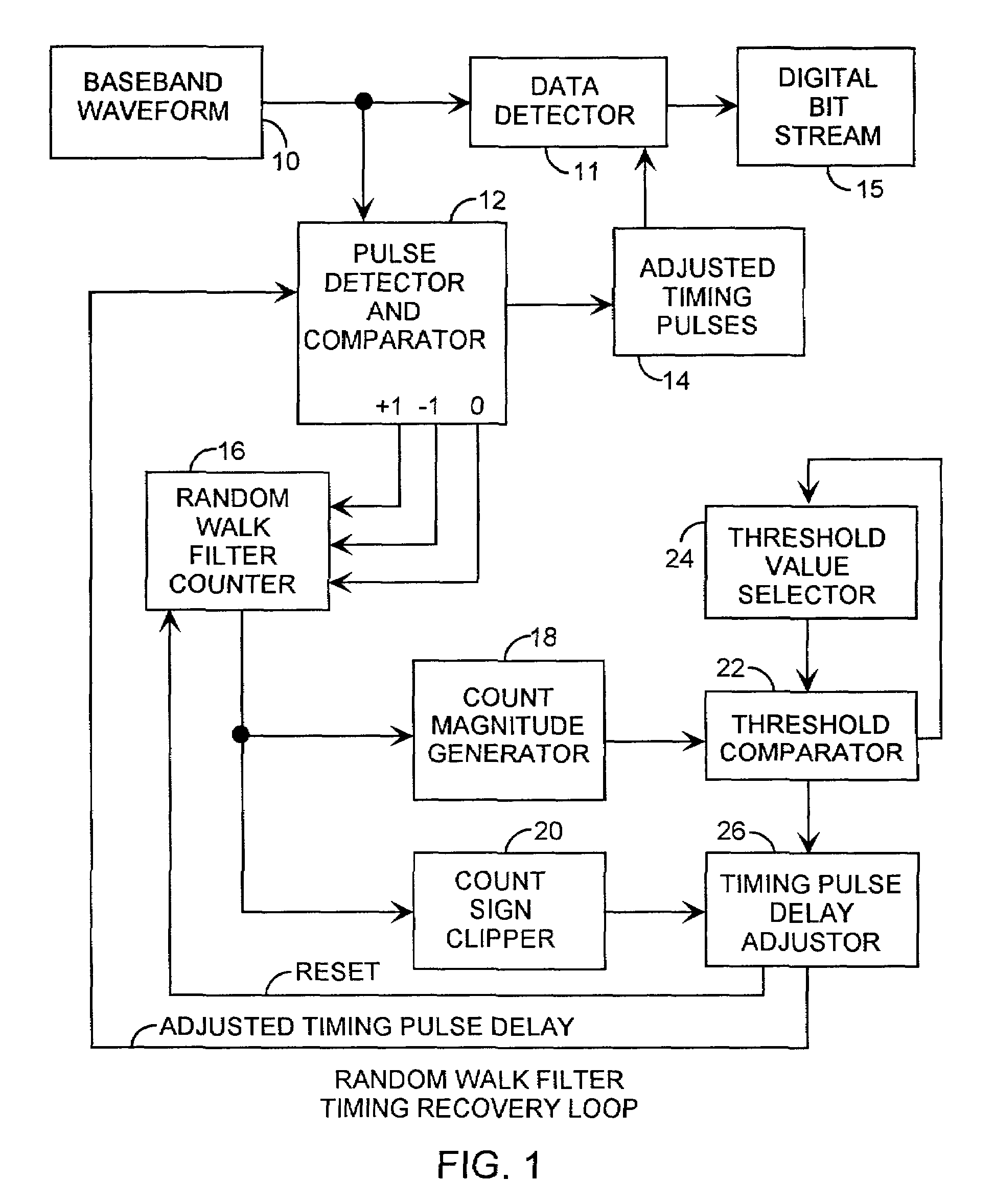
[0011]The invention is directed to a timing recovery loop enhanced with a random walk filter. The enhanced timing recovery loop achieves improvement in reduced timing jitter. A setable error threshold enables adaptive synchronization in the timing recovery loop, reduces drop lock rates and decreases the acquisition time. The dropped-lock rate is less frequent due to the setting of the threshold value of the random walk filter timing recovery loop. The threshold value can be adaptively reset. The random walk filter timing recovery loop provides faster acquisition time by adaptively setting the threshold value to changing channel environments. As an example, the threshold value can be based on the frequency of the adjustments to the generated timing pulses so as to provide responsive and yet not overly jittery adjustments.

Problems solved by technology

The baseband signal waveform is subject to channel noise leading to poorly generated timing pulses and hence poor bit timing resulting in poor data detection.
After dropping lock, the conventional timing recovery loops disadvantageously experience long hang up time due to the need to reacquire the timing pulses.
Although used for decades, random walk filters have not been adapted to improving the bit clock locking stability in timing recovery loops.
Existing timing recover loops suffer from drop of bit timing lock in noisy channels.
Noisy channels suffer from ambiguous bit timing transitions leading to jittering and inaccurate timing pulses.

Method used


Image

  • Random walk filter timing recovery loop
  • Random walk filter timing recovery loop
  • Random walk filter timing recovery loop

Examples


Embodiment Construction

[0016]An embodiment of the invention is described with reference to the figures using reference designations as shown in the figures. Referring to FIG. 1, a baseband signal waveform 10 carries an input digital bit stream of encoded data. The binary data and timing are encoded into the baseband signal waveform 10. The baseband signal waveform 10 is fed into a conventional data detector 11 and a pulse detector and comparator 12. The pulse detector and comparator 12 generates adjusted timing pulses 14 that can be used by the data detector 11 to sample the baseband signal waveform 10 to reconstruct the digital bit stream 15. The baseband signal waveform 10 has been carrier-demodulated.

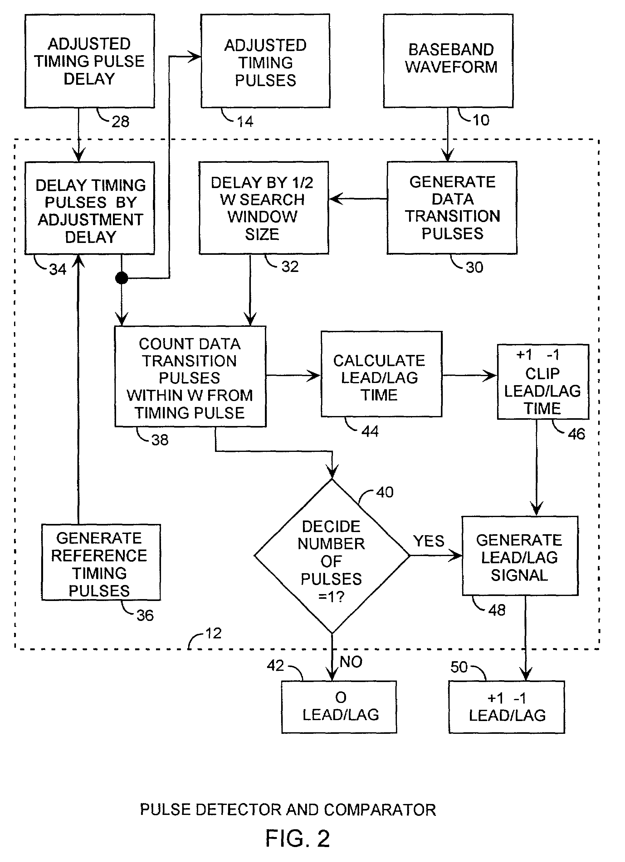
[0017]The pulse detector and comparator 12 receives the baseband signal waveform 10 and generates the adjusted timing pulses 14. The data may be encoding onto the baseband signal in several different types of formats, such as binary pulse shift keying (BPSK). For example, BPSK encoding has zero crossings a...


PUM


Abstract

A timing recovery loop includes a random walk filter counter for counting early, nominal and late arrivals of data transitions pulses of an input baseband signal waveform encoding a digital bit stream, and provides magnitude counts that are compared to a threshold value that when exceeded by the magnitude counts results in a delay adjustment of the generated adjusted timing pulses then remaining synchronized with the actual bit timing for maintaining bit timing lock. The adjusted timing pulses can then be used by a data detector for reliable data detection and reconstruction of the digital bit stream. The threshold value can be adaptively adjusted for reducing drop lock rates in the presence of changing channel environments.

Description

STATEMENT OF GOVERNMENT INTEREST[0001]The invention was made with Government support under contract No. F04701-00-C-0009 by the Department of the Air Force. The Government has certain rights in the invention.FIELD OF THE INVENTION[0002]The invention relates to the field of digital communications. More particularly, the present invention relates to timing recovery loops for accurate detection and tracking of binary data streams.BACKGROUND OF THE INVENTION[0003]In a communication receiver, a received RF signal is demodulated to generate a baseband signal waveform containing a self-clocking bit stream of digital data. The baseband signal waveform is tracked using a timing recovery loop. The timing recovery loop tracks bit timing of the baseband signal waveform and generates timing pulses, which are then used in a data detector for sampling the baseband signal waveform at the bit intervals for reconstructing the digital bit stream from the received baseband signal waveform. The baseband...

Claims


Application Information

Patent Timeline
Patent Type & Authority Patents(United States)
IPC IPC(8): H04L25/38H03D3/22H04L7/033
CPCH04L7/0331
Inventor NGUYEN, TIEN M.YOH, JAMESMATHUR, ASHOKGOO, GARY W.
Owner THE AEROSPACE CORPORATION
Learn More