Retardation compensator and single-panel type color liquid crystal projector
a liquid crystal projector and compensator technology, applied in the direction of color television details, instruments, polarising elements, etc., can solve the problems of inability to increase the contrast ratio of the projected image, the projection lens system is disadvantageous in the way of making the projector smaller, and the liquid crystal device has the disadvantage of narrow viewing angle, etc., to improve the contrast ratio and the color balance of the image. , the effect of low manufacturing cos
- Summary
- Abstract
- Description
- Claims
- Application Information
AI Technical Summary
Benefits of technology
Problems solved by technology
Method used
Image
Examples
embodiment 1
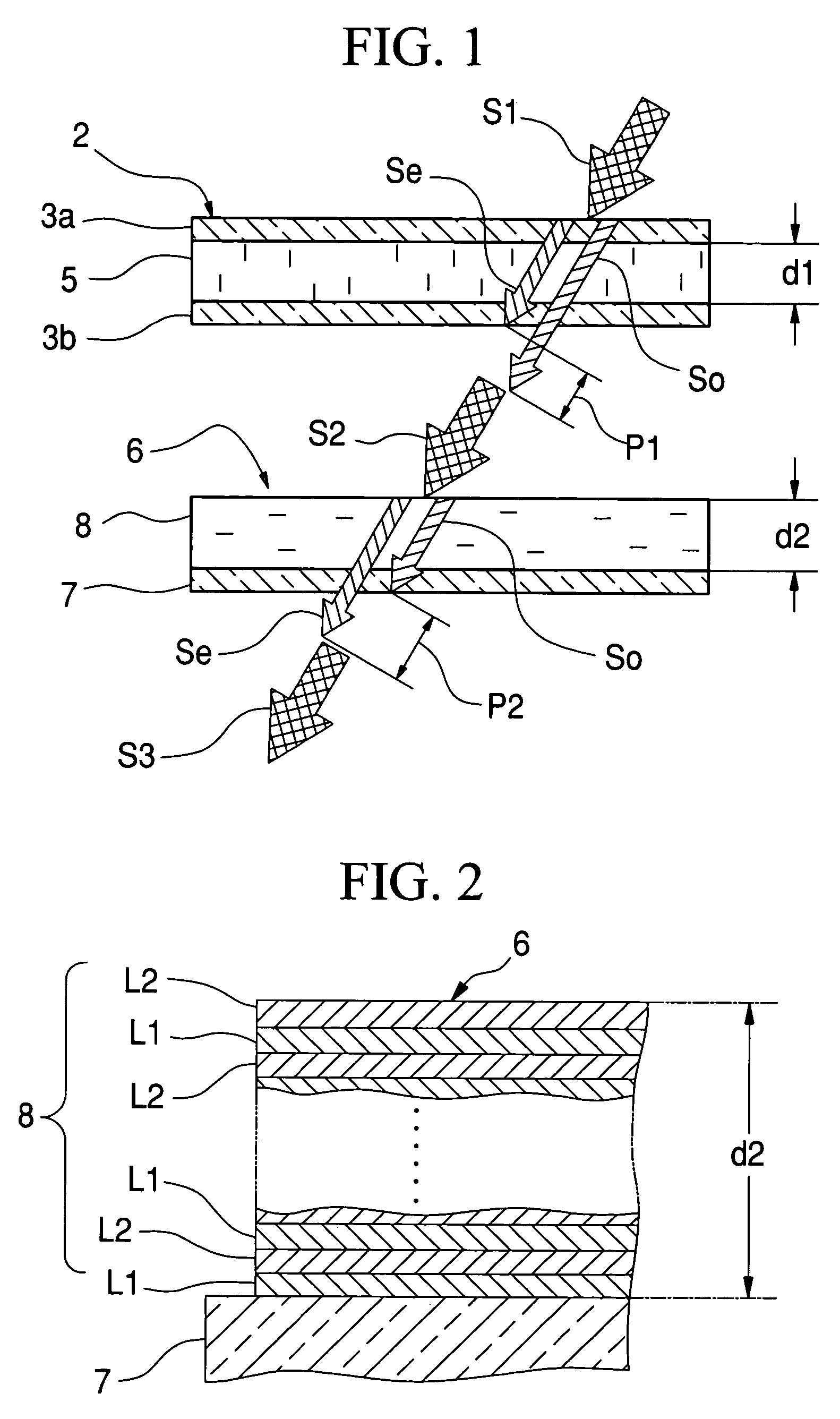
[0086]As shown in FIG. 7, the retardation d·Δn of nematic liquid crystal material for the TN liquid crystal device has wavelength dependence. Note that the thickness d of the TN liquid crystal device (corresponding to d1 of the liquid crystal layer 5 in FIG. 1) is 4.5 μm. Since all of the liquid crystal molecules in a black state pixel do not orientate perpendicularly, as mentioned above, it is assumed that 70% of the liquid crystal molecules in thickness d cause effective retardation Re to be compensated. The effective retardation Re, calculated by 0.7×d·Δn, is also listed in FIG. 7.
[0087]In this embodiment, the liquid crystal device contains cyanocyclohexanes nematic liquid crystal, known as “ZLI-1083” (Trade Name) manufactured by Merck Ltd. The rate of the liquid crystal molecules to cause the effective retardation is not limited to 70%, but may be decided appropriately in accordance with composition and kind of the liquid crystal molecules, applied voltage to the substrates and ...
embodiment 2
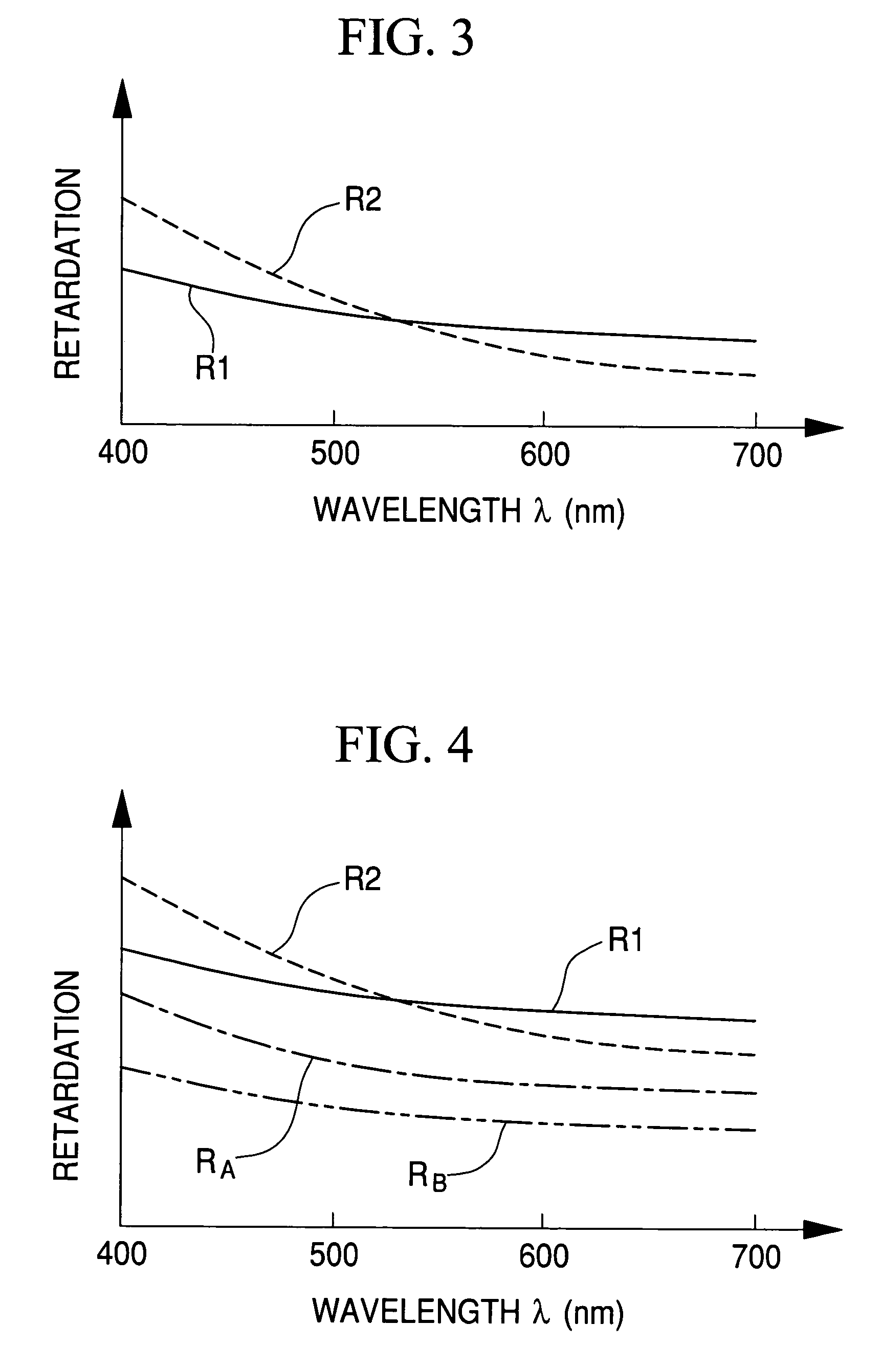
[0095]FIG. 10 shows the physical properties of the retardation compensation film (2) that is composed of 51 LiNbO3 film layers and 51 SiO2 film layers that are alternately layered on a substrate. The LiNbO3 film layer is used as the high refractive index layer, whereas The SiO2 film layer is used as the low refractive index layer. The physical thicknesses of the LiNbO3 film layer and the SiO2 film layer are 27.5 nm and 22.5 nm, respectively. The physical thickness of the retardation compensation film (2) is 2.55 μm in total. Compared with the Embodiment 1, the birefringence value Δn of the retardation compensation film (2) is smaller, because the refractive index of the LiNbO3 film layer is smaller than that of the TiO2 film layer. However, the wavelength dependence of the retardation compensation film (2) has improved. Referring to FIG. 11 that shows the graph of the wavelength dependence, the retardation (▴) of the retardation compensation film (2) is almost the same as the effect...
embodiment 3
[0096]FIG. 12 shows the physical properties of the retardation compensation film (3) that is composed of LiNbO3 film layers and MgF2 film layers that are alternately layered on a substrate. The LiNbO3 film layer is used as the high refractive index layer, whereas the MgF2 film layer is used as the low refractive index layer. The thickness and the number of the LiNbO3 film layer and MgF2 film layer are the same embodiment 1. Referring to FIG. 13 that shows the graph of the wavelength dependence, it is found that the retardation compensation film (3) has the similar retardation compensation characteristics as the retardation compensation film (2) according to Embodiment 2.
[0097]As mentioned in the above embodiments, the birefringence value Δn of the retardation compensation film 8 becomes large as the difference in the refractive indices between high and low refractive index layers increases. Thus, when the physical thickness of each layer is constant, increasing the difference in the...
PUM
| Property | Measurement | Unit |
|---|---|---|
| thickness | aaaaa | aaaaa |
| thickness ratio | aaaaa | aaaaa |
| thickness ratio | aaaaa | aaaaa |
Abstract
Description
Claims
Application Information
 - R&D
- Intellectual Property
- Life Sciences
- Materials
- Tech Scout
- Unparalleled Data Quality
- Higher Quality Content
- 60% Fewer Hallucinations
Browse by: Latest US Patents, China's latest patents, Technical Efficacy Thesaurus, Application Domain, Technology Topic, Popular Technical Reports.
© 2025 PatSnap. All rights reserved.Legal|Privacy policy|Modern Slavery Act Transparency Statement|Sitemap|About US| Contact US: help@patsnap.com


