Scroll-type fluid displacement apparatus with fully compliant floating scrolls
a fluid displacement apparatus and scroll technology, applied in the direction of liquid fuel engines, rotary/oscillating piston pump components, machines/engines, etc., can solve the problems of high production cost, non-traditional thrust bearings are technically complicated and expensive, and fast wear of parts, so as to reduce friction wear and loss
- Summary
- Abstract
- Description
- Claims
- Application Information
AI Technical Summary
Benefits of technology
Problems solved by technology
Method used
Image
Examples
first embodiment
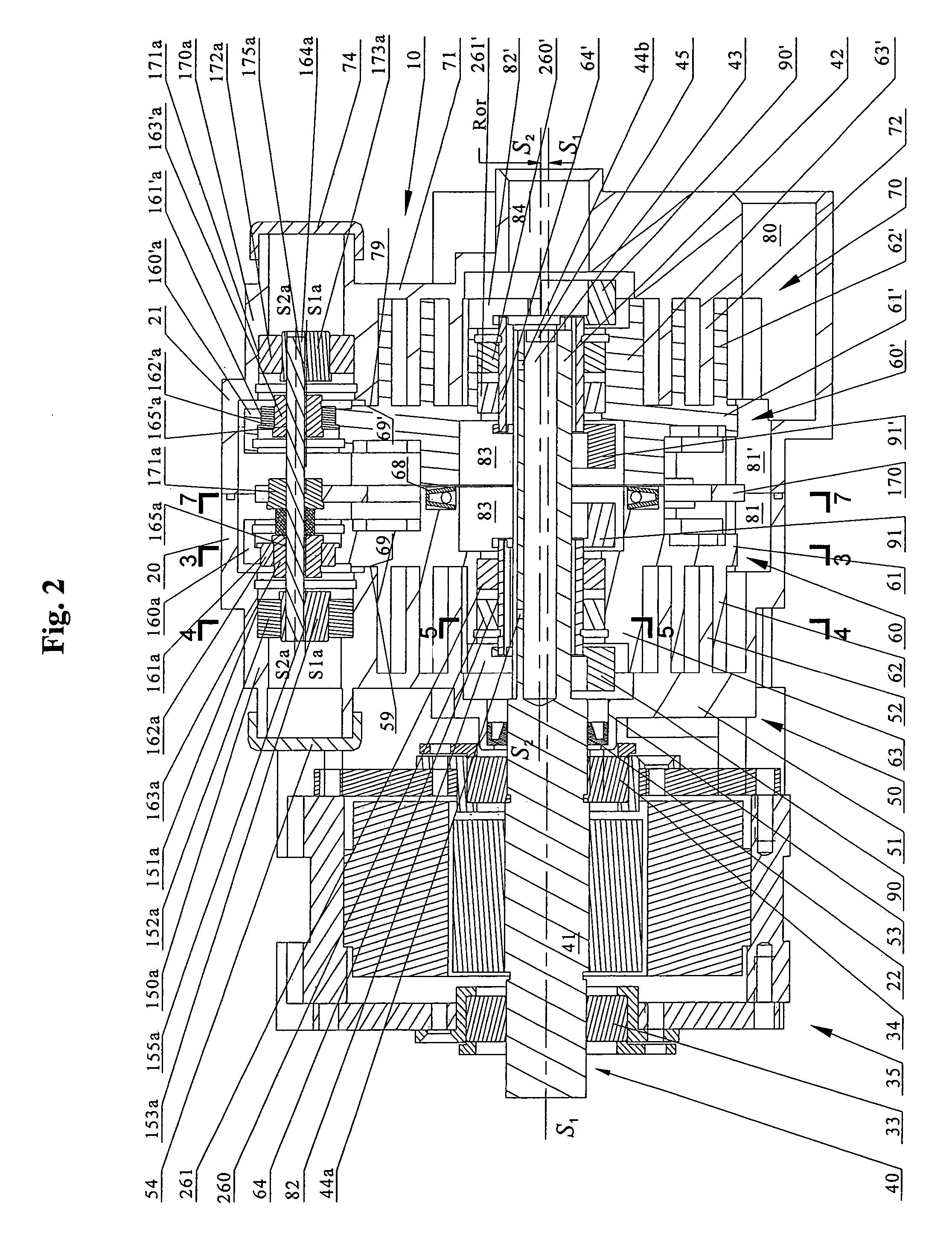
[0048]The CSPS mechanism can also be applied in single floating scroll structure. a single floating scroll compressor with CSPS mechanism is shown in FIG. 8. In a single floating scroll structure the CSPS mechanism may be seen as a half of the mechanism in a dual scroll structure. The difference is that the plenum seal 68 (see FIG. 2) is static in a dual floating scroll structure, but dynamic in a single floating scroll structure (68 in FIG. 8).
[0049]Referring to FIG. 8, the compressor unit 10 includes a main housing 20, base housing 70, hermetic sealed motor 35, central drive shaft 40, fixed scroll 50 and orbiting scroll 60. Central drive shaft 40 consists of central rod 41 and crank pin 42. Central rod 41 is rotatably supported by bearing 33 and 34, and rotates along its axis S1-S1 when driven by hermetic sealed motor 35. An axial hole 43 in the middle of crank pin 42 is to balance the centrifugal force of the crank pin 42 when shaft 40 rotates along axis S1-S1. Hole 43 can also s...
second embodiment
[0057]Referring to FIG. 9, in the second embodiment the plenum sealing mechanism comprises of an orbiting moving piston 68, an “O” ring 71 and spring 72. The orbiting moving piston 68, energized by spring 72 and air at discharge pressure in plenum chamber 83, can move axially and orbits together with orbiting scroll 60 against surface 73 of base housing 70. This mechanism seals off plenum 83 from suction area 81. Orbiting moving piston 68 is self-compensate to improve the life of the sealing mechanism.
[0058]In the third embodiment of single floating scroll of CSPS mechanism with a stationary moving piston seal mechanism as shown in FIG. 10, the plenum sealing elements, i.e. moving piston 71 and “O” ring 72, are stationary instead of orbiting together with orbiting scroll 60 as in the first and second embodiments. Sealing surface 73 of piston 71 energized by “O” ring 72 keeps light contact with sealing surface 65 of orbiting endplate 61 during operation. This mechanism seals off plen...
fourth embodiment
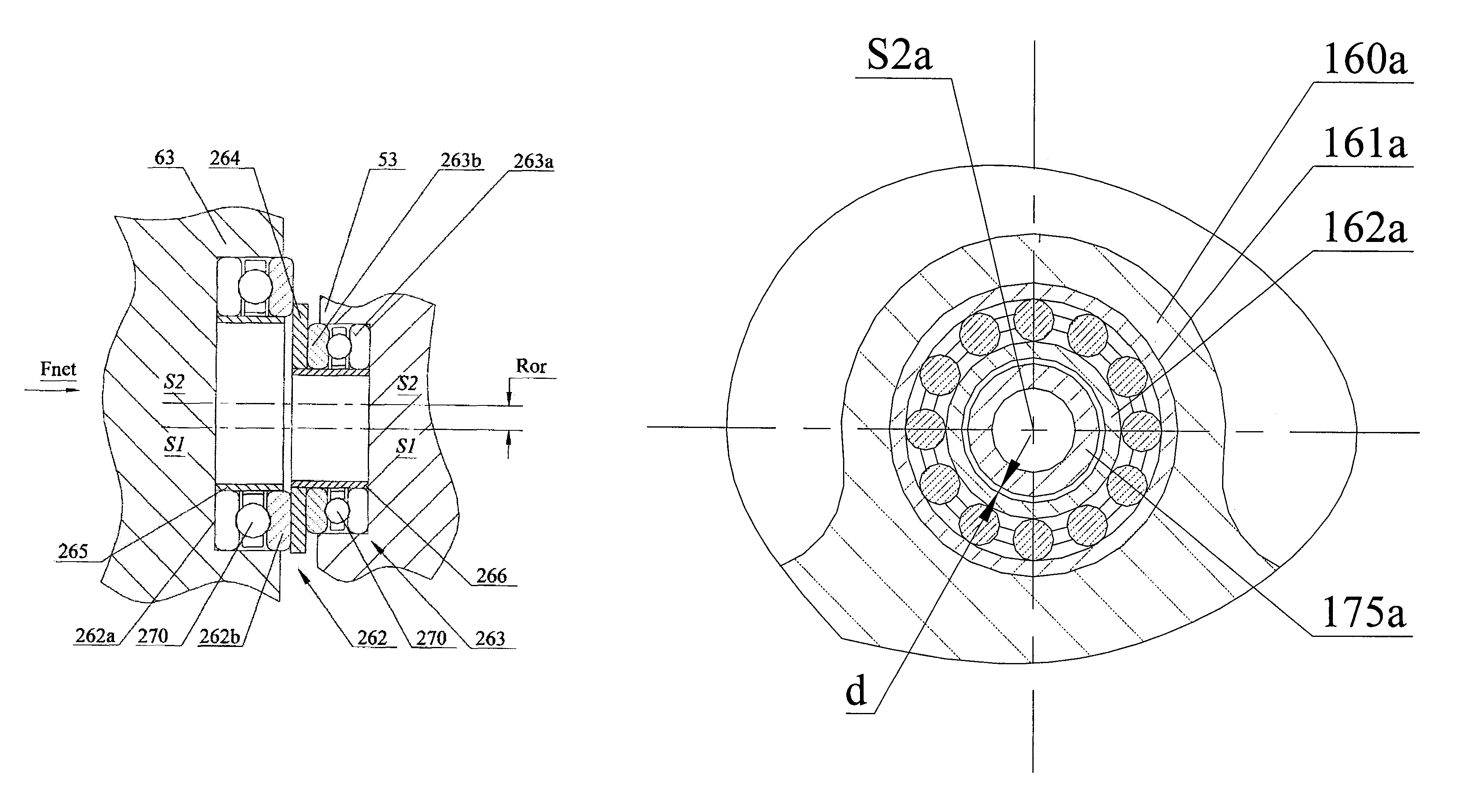
[0059]The friction wear and friction power loss resulted from axial forces in a floating scroll device, particularly when the pressure differential between the discharge gas and the suction gas is large, needs to be further reduced to improve the energy efficiency and durability. the single floating scroll device, an expander as shown in FIG. 11, provides an orbiting dual thrust ball bearing structure to bear the thrust load on orbiting scroll with a semi-radial compliant CSPS mechanism.
[0060]Referring to FIG. 11 expander unit 10 includes a main housing 20, rear housing 21, base housing 70, central drive shaft 40, fixed scroll 50 and orbiting scroll 60. Central drive shaft 40 consists of central rod 41 and crank rod 42. Central rod 41 is rotatably supported by bearing 33 and 34, and rotates along its axis S1-S1. Fixed scroll member 50 has an end plate 51 from which a scroll element 52 extends. Orbiting scroll member 60 includes circular end plate 61, scroll element 62 affixed to and...
PUM
 Abstract
Description
Claims
Application Information
 - R&D
- Intellectual Property
- Life Sciences
- Materials
- Tech Scout
- Unparalleled Data Quality
- Higher Quality Content
- 60% Fewer Hallucinations
Browse by: Latest US Patents, China's latest patents, Technical Efficacy Thesaurus, Application Domain, Technology Topic, Popular Technical Reports.
© 2025 PatSnap. All rights reserved.Legal|Privacy policy|Modern Slavery Act Transparency Statement|Sitemap|About US| Contact US: help@patsnap.com


