
Loudspeaker system

a speaker system and loudspeaker technology, applied in the direction of deaf-aid sets, electrical transducers, transducer details, etc., can solve the problems of difficulty in realizing a speaker system capable of reproducing low frequency sound, and achieve the effects of low air permeability, easy moisture prevention, and large capacity

Active Publication Date: 2008-12-09
PANASONIC CORP
View PDF14 Cites 35 Cited by
  • Summary
  • Abstract
  • Description
  • Claims
  • Application Information

AI Technical Summary

Benefits of technology

"The present invention is about a loudspeaker system that can effectively reproduce low-frequency sounds while maintaining the physical absorption capability of the system. The system includes a cabinet, a loudspeaker unit, an absorbent, and a phase inverting mechanism. The absorbent is located inside the hollow chamber of the cabinet and physically absorbs a gas present in the hollow chamber. The phase inverting mechanism inverts the phase by resonating with a sound of a specific frequency radiated from the loudspeaker unit and radiates it to outside. The system also includes watertight means to prevent moisture from invading from the outside of the cabinet. The technical effect of the invention is to provide a compact-size loudspeaker system that can effectively reproduce low-frequency sounds while maintaining the physical absorption capability of the system."

Problems solved by technology

Due to the influence of the acoustic stiffness inherent to a hollow chamber of a speaker cabinet, it is generally difficult to realize a speaker system which is capable of reproducing a low frequency sound using a compact-size loudspeaker system.

Method used


Image

  • Loudspeaker system
  • Loudspeaker system
  • Loudspeaker system

Examples


first embodiment

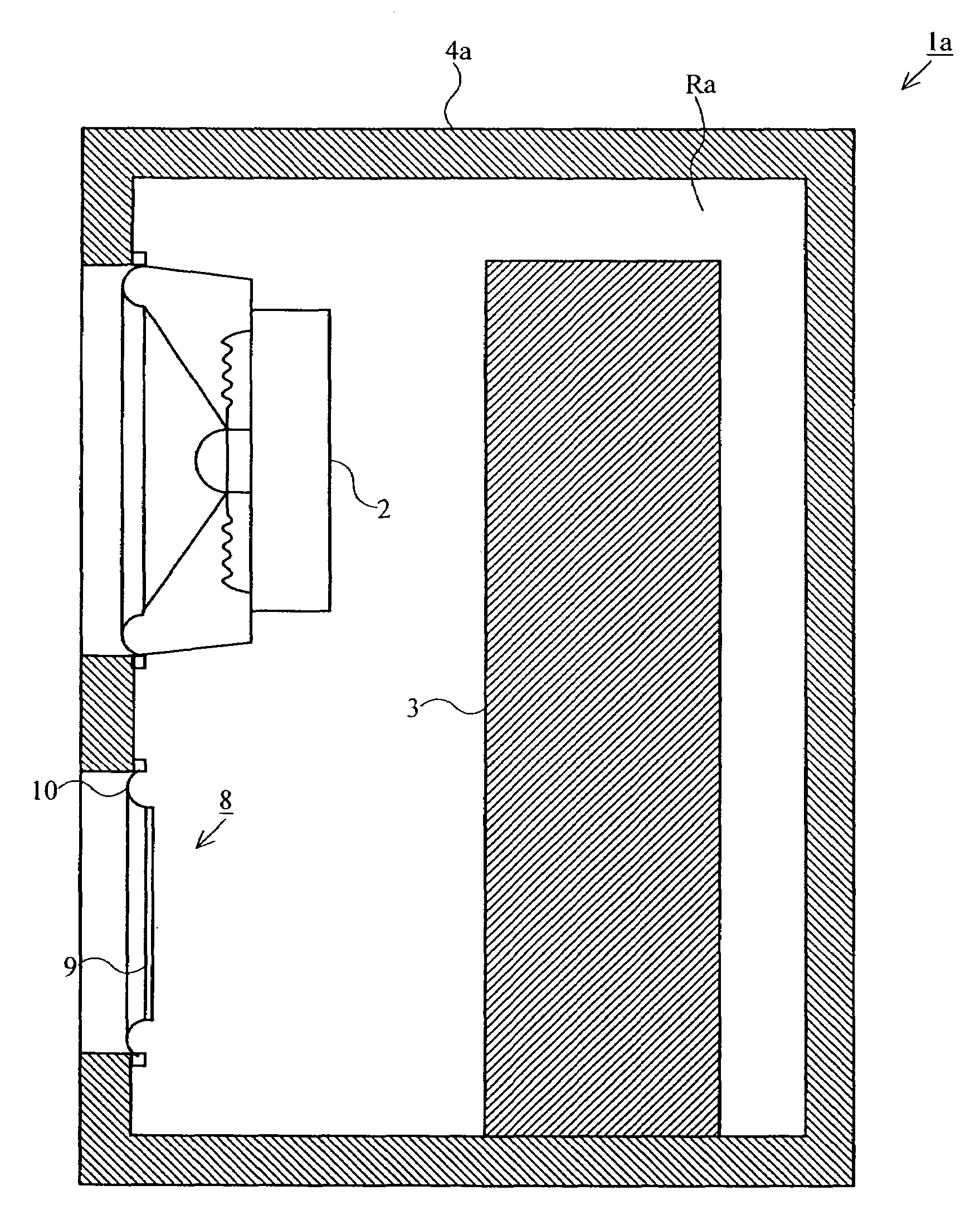
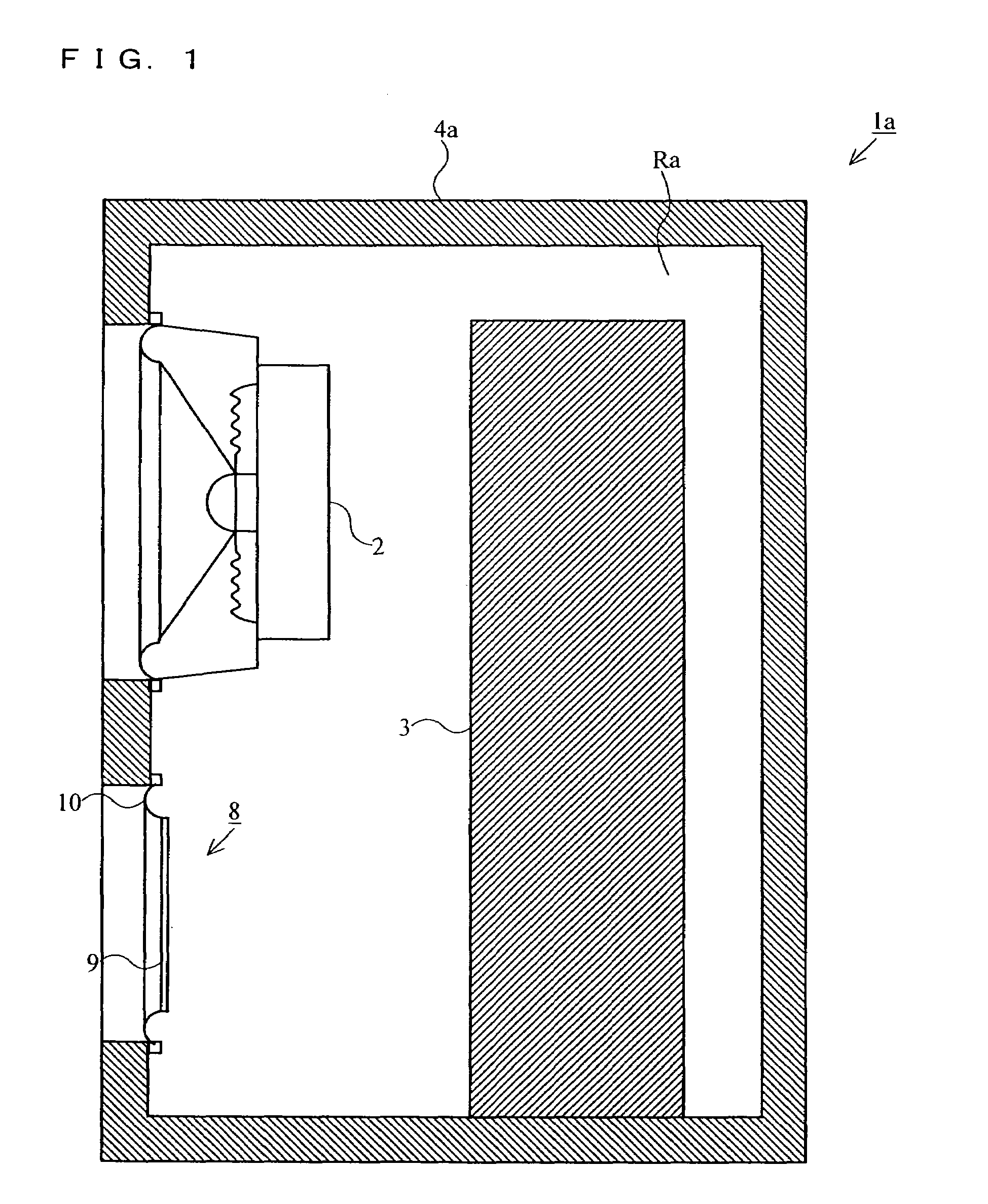
[0045]With reference to FIG. 1, the loudspeaker system according to the first embodiment of the present invention will now be described. The loudspeaker system according to the first embodiment uses a passive radiator (drone cone) system as one example of the phase inversion mode. FIG. 1 is a cross sectional view which schematically shows the internal structure of the loudspeaker system 1a.

[0046]In FIG. 1, the loudspeaker system 1a comprises a loudspeaker unit 2, an absorbent 3, a cabinet 4a and a drone cone 8. The cabinet 4a forms the front surface, the back surface, the top surface, the bottom surface and the side surfaces of the right-hand side and the left-hand side of a housing of the loudspeaker system 1a. The loudspeaker unit 2 is an electrodynamic speaker and fitted to an opening of the front surface of the cabinet 4a. Inside the cabinet 4a, a hollow chamber Ra of the loudspeaker system 1a is created.

[0047]The absorbent 3 is disposed inside the hollow chamber Ra. The absorb...

second embodiment

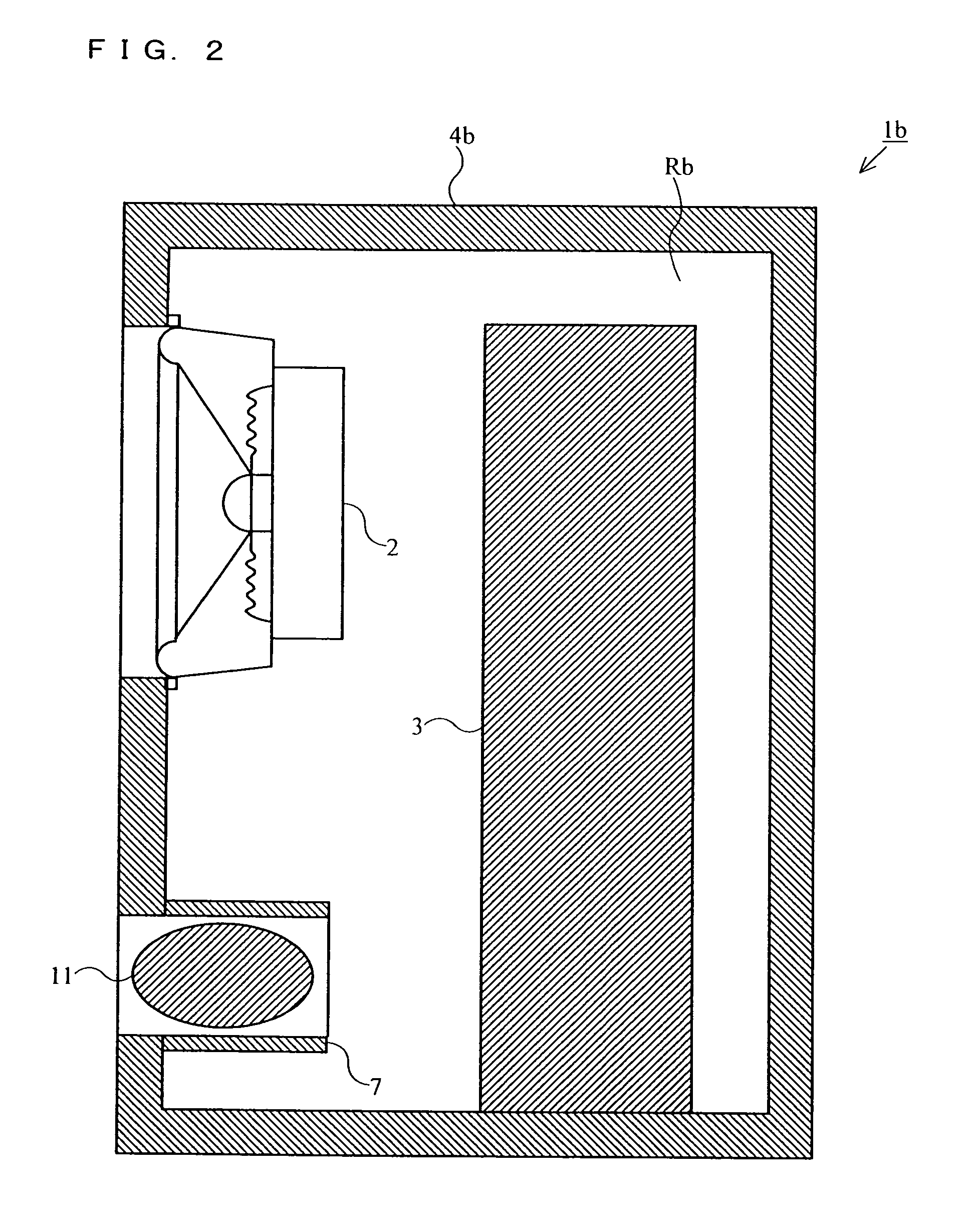
[0052]With reference to FIG. 2, the loudspeaker system according to the second embodiment of the present invention will now be described. The loudspeaker system according to the second embodiment uses a bass reflex-type loudspeaker system as one example of the phase inversion mode. FIG. 2 is a cross sectional view which schematically shows the internal structure of this loudspeaker system 1b.

[0053]In FIG. 2, the loudspeaker system 1b comprises a loudspeaker unit 2, an absorbent 3, a cabinet 4b, an acoustic port 7 and a damp proofing agent 11. The cabinet 4b forms the front surface, the back surface, the top surface, the bottom surface and the side surfaces of the right-hand side and the left-hand side of a housing of the loudspeaker system 1b. The loudspeaker unit 2 is an electrodynamic speaker and fitted to an opening of the front surface of the cabinet 4b. Inside the cabinet 4b, a hollow chamber Rb of the loudspeaker system 1b is created.

[0054]The absorbent 3 is disposed inside t...


PUM


Abstract

A loudspeaker unit (2) of a loudspeaker system (1) is fitted to a cabinet (4). An absorbent (3) is disposed in a hollow chamber (R) inside the cabinet (4) and absorbs a gas inside the hollow chamber (R). A phase inverting mechanism (8) inverts the phase by resonating with a sound of a specific frequency radiated from the loudspeaker unit (2) into the hollow chamber (R) and radiates this sound to outside. The watertight means of the phase inverting mechanism (8) prevents invasion of moisture into inside the hollow chamber (R) from outside the cabinet (4) through the phase inverting mechanism (8).

Description

TECHNICAL FIELD[0001]The present invention relates to a loudspeaker system, and more particularly, to a loudspeaker system which reproduces a low frequency sound with a compact-size speaker cabinet.BACKGROUND ART[0002]Due to the influence of the acoustic stiffness inherent to a hollow chamber of a speaker cabinet, it is generally difficult to realize a speaker system which is capable of reproducing a low frequency sound using a compact-size loudspeaker system. In an attempt to realize reproduction of a low frequency sound with a compact-size loudspeaker system, an airtight loudspeaker system whose cabinet houses a lump of activated carbon inside is known as means which solves the problem that the capacity of a cabinet sets a limit upon reproduction of a low frequency sound. (See Patent Document 1 for instance.)[0003]FIG. 10 is a cross sectional view which shows the structure of an essential part of the loudspeaker system described in Patent Document 1 mentioned above. In FIG. 10, th...

Claims


Application Information

Patent Timeline
Patent Type & Authority Patents(United States)
IPC IPC(8): H04R25/00H04R1/00H04R1/02H04R1/28
CPCH04R1/2819H04R1/2834H04R1/2803
Inventor KUZE, MITSUKAZUSAIKI, SHUJIKANO, SAWAKOMATSUMURA, TOSHIYUKI
Owner PANASONIC CORP
Learn More