Optical fiber birefringence measurement method and measurement device, and optical fiber polarization mode dispersion measurement method and optical fiber

a measurement method and optical fiber technology, applied in the direction of measurement devices, testing fibre optics/optical waveguide devices, instruments, etc., can solve the problems of limited use of such methods, substantial waste, and considerable torsion, and achieve the effect of short tim

Inactive Publication Date: 2008-12-09
THE FUJIKURA CABLE WORKS LTD
View PDF12 Cites 5 Cited by
  • Summary
  • Abstract
  • Description
  • Claims
  • Application Information

AI Technical Summary

Benefits of technology

[0025]This invention was devised in light of the above circumstances, and has as an object the provision of a method of measurement, with accuracy and in a short length of time, of the birefringence and PMD of a short optical fiber having a comparatively small PMD in the free state and a device therefore.
[0038]In the polarization mode dispersion measurement method, cushion material may be positioned at a place at which the optical fiber for measurement is in contact with the bobbin around which the optical fiber is wound, to reduce lateral pressure on the optical fiber, and in addition the effect of polarization state fluctuations during measurements arising from expansion and shrinkage of the bobbin due to temperature changes in the measurement environment may be eliminated.
[0043]According to this invention, the round-trip Jones matrix R(z) for a first interval (0,z) from a measurement starting point 0 in the optical fiber for measurement to a prescribed position z and the round-trip Jones matrix R(z+Δz) for a second interval (0, z+Δz) from the measurement starting point 0 to a position z+Δz differing from the position z in the optical fiber for measurement are acquired, the eigenvalues ρ1, ρ2 of the matrix R(z+Δz)R(z)−1 are determined, and the birefringence of the infinitesimal interval Δz is obtained by calculation, and, the PMD of the optical fiber is obtained from the optical fiber birefringence thus obtained, so that a method and device for the accurate measurement, in a short length of time, of the birefringence and PMD of a short optical fiber, in the free state and having comparatively small PMD, can be provided.

Problems solved by technology

But an optical fiber wound on a bobbin is subject to bending and to birefringence caused by lateral pressure while wound on the bobbin; in addition, optical fibers will come into contact with each other or will be subjected to considerable torsion while being taken up on the bobbin, so that polarization mode coupling is induced.
However, there are the following problems with the PMD measurement methods of the prior art.
In order to increase the total PMD of the optical fiber for measurement, the total length of the optical fiber for measurement must be made long if the optical fiber for measurement has a small PMD; but because an optical fiber used in PMD measurements in the free state cannot again be used as a product, this method requires a long optical fiber each time a measurement is performed, so that waste is substantial.
Further, methods entailing expansion of the wavelengths for measurement are subject to constraints imposed by the operating wavelengths of the light source, and so there are limits to the use of such methods.
And, methods requiring a plurality of measurements require time to perform measurements and are inefficient.
Because there are large fluctuations in PMD depending on the preform and drawing conditions of the optical fiber, normally optical fibers manufactured under identical conditions exhibit substantially the same PMD value, but due to unanticipated causes, there are cases of partial worsening of the PMD, and so it is desirable that length-direction measurements be performed.
First, in methods of the prior art, the waveform amplitude differs depending on the incident polarization state and on the birefringence axis angle of the optical fiber, and so there is the problem that measurements cannot be performed accurately. For example, when the incident polarization is linear polarization, the amplitude is maximum when the angle between the direction of linear polarization and the birefringence axis is 45°, but when the two directions coincide, the amplitude is zero. This problem has a serious impact on the results of measurement of polarization mode dispersion using conventional methods.
Further, in methods of the prior art, scattering from the least-square approximating line is used as an index of the scattering in the OTDR waveform; to this end, averaging must be performed over a certain interval, and so it is inherently not possible to obtain a high resolution.
Moreover, a feature of methods of the prior art is the simple configuration obtained by using a general-purpose OTDR; but because the light source of a general-purpose OTDR has a broad spectral width from 5 nm to 20 nm, once a point with large PMD is traversed, a phenomenon occurs in which the polarization state of the pulse differs with the wavelength, and so the amplitude is averaged and becomes smaller; hence there is the problem that subsequent PMD measurements cannot be performed (see Non-patent Reference 1).

Method used


Image

  • Optical fiber birefringence measurement method and measurement device, and optical fiber polarization mode dispersion measurement method and optical fiber
  • Optical fiber birefringence measurement method and measurement device, and optical fiber polarization mode dispersion measurement method and optical fiber
  • Optical fiber birefringence measurement method and measurement device, and optical fiber polarization mode dispersion measurement method and optical fiber

Examples


Embodiment Construction

[0067]Below, preferred embodiments of the invention are explained, referring to the drawings. However, the invention is not limited to the following embodiments, and for example constituent elements of these embodiments may be appropriately combined.

[0068]First, a method of measurement of birefringence of an optical fiber according to this invention is explained.

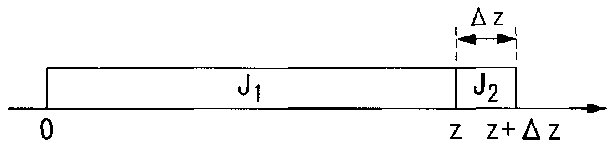
[0069]FIG. 1 is a summary diagram to explain the measurement interval in an optical fiber birefringence measurement method of this invention. In the birefringence measurement method of the invention, a first interval (0, z) is set from a measurement starting point 0 to a prescribed position z in the optical fiber for measurement, and a second interval (0, z+Δz) from the measurement starting point 0 to a position z+Δz different from the position z is set; the interval from the position z to the position z+Δz (the interval which is the difference between the first interval and the second interval) is the infinitesimal interval...


PUM

PropertyMeasurementUnit
diameteraaaaaaaaaa
widthaaaaaaaaaa
spectral widthaaaaaaaaaa

Abstract

In a method of measurement of the birefringence of an optical fiber, the round-trip Jones matrix R(z) for a first interval (0, z) from a measurement starting point 0 in the optical fiber for measurement to a prescribed position z, and the round-trip Jones matrix R(z+Δz) for a second interval (0, z+Δz) from the measurement starting point 0 to a position z+Δz differing from the position z, are acquired, the eigenvalues ρ1, ρ2 of the matrix R(z+Δz)R(z)−1 are determined, and by computing the following equations (1) and (2),ϕ=arg⁡(ρ1ρ2)2(1)Δ⁢⁢n=λϕ2⁢π·Δ⁢⁢z(2)(where φ represents the phase difference between linear polarization components due to birefringence, Δn represents birefringence, and λ represents wavelength), the birefringence in the infinitesimal interval Δz from the position z to the position z+Δz is obtained.

Description

BACKGROUND OF THE INVENTION[0001]1. Field of the Invention[0002]This invention relates to a method of measurement of birefringence of an optical fiber and a measurement device, and to an optical fiber polarization mode dispersion measurement method and an optical fiber, and relates to techniques for the precise and simple measurement of the birefringence and polarization mode dispersion of an optical fiber along the length direction.[0003]This application relates to and claims priority from Japanese Patent Application No. 2005-117030, filed on Apr. 14, 2005, and from Japanese Patent Application No. 2005-229263, filed on Aug. 8, 2005, the entire disclosures of which are incorporated herein by reference.[0004]2. Description of the Related Art[0005]In recent years, the faster transmission rates and longer transmission distances of optical communications have been accompanied by a need to reduce polarization mode dispersion (hereafter “PMD”) along transmission paths. PMD is dispersion w...

Claims


Application Information

Patent Timeline
Patent Type & Authority Patents(United States)
IPC IPC(8): G01N21/00
CPCG01M11/3145G01M11/3181
Inventor GOTO, RYUICHIROMATSUO, SHOICHIROHIMENO, KUNIHARU
Owner THE FUJIKURA CABLE WORKS LTD
Why Eureka
Try Eureka