Probe for electrical measurement methods, especially eddy current measurements

a technology of eddy current measurement and probe, which is applied in the direction of magnetic property measurement, material magnetic variable, instruments, etc., can solve problems such as inability to obtain correct measured values

Inactive Publication Date: 2008-12-09
SIEMENS AG
View PDF8 Cites 2 Cited by
  • Summary
  • Abstract
  • Description
  • Claims
  • Application Information

AI Technical Summary

Benefits of technology

[0013]A polymer film which is filled with a ferrite is advantageously used for the backing, so that a ferromagnetic signal amplification is advantageously possible.

Problems solved by technology

In the case of non-planar surfaces, the probe must be adapted in its shape to a surface of the test piece; otherwise, incorrect measured values are obtained.

Method used


Image

  • Probe for electrical measurement methods, especially eddy current measurements
  • Probe for electrical measurement methods, especially eddy current measurements

Examples


Embodiment Construction

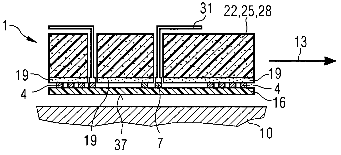
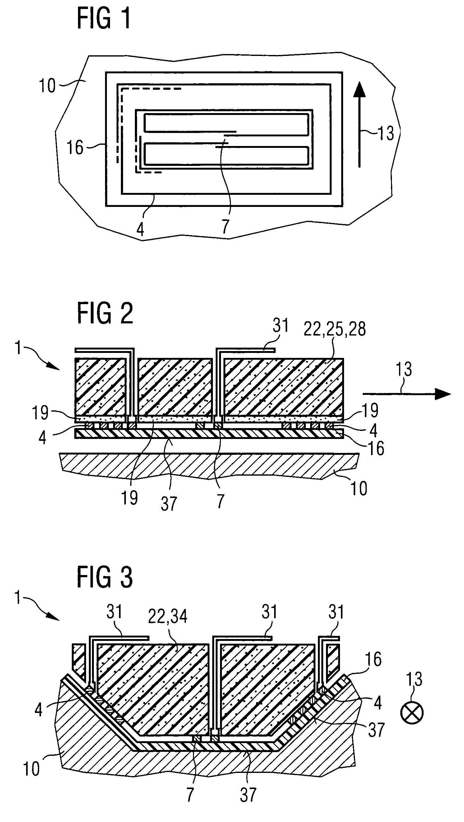
[0020]FIG. 1 shows an exciter coil 4 and a signal coil 7 as electrical components in their arrangement in one plane according to the prior art.

[0021]The signal coil 7 is, for example, surrounded by the exciter coil 4. With respect to the further exemplary construction of the exciter coil 4, signal coil 7 and an evaluation system with a probe, reference is made to DE 197 48 556 A1, which is expressly intended to form part of this disclosure.

[0022]The exciter coil 4 and signal coil 7 are electrically separated from each other. The signal coil 7 is in this example designed as a differential probe. The local resolution is determined by the distance between the the two coil sections, the so-called baseline.

[0023]The exciter winding 4 encloses the coil sections of the signal coil 7, for example symmetrically, so that a compensation of the exciter field is ensured. The exciter winding 4 and the signal coil 7 consequently lie in one plane or on the same surface of the substrate 16. Exemplar...


PUM

PropertyMeasurementUnit
thicknessaaaaaaaaaa
thicknessaaaaaaaaaa
thicknessaaaaaaaaaa

Abstract

When using a rigid substrate eddy current probe to measure a non-planer test piece, the probe must be adapted to the test piece shape in order to avoid incorrect measurement values. Disclosed is a probe which is configured in a flexible manner via a flexible substrate so as to be adjustable to different radii of curvature of a test piece. Furthermore the probe lining is also embodied in an elastic manner.

Description

CROSS REFERENCE TO RELATED APPLICATION[0001]This application is the US National Stage of International Application No. PCT / EP2004 / 006792, filed Jun. 23, 2004 and claims the benefit thereof. The International Application claims the benefits of European Patent application No. 03015494.2 EP filed Jul. 9, 2003, both of the applications are incorporated by reference herein in their entirety.FIELD OF THE INVENTION[0002]The invention is based on a probe for electrical measurement methods according to the claims.BACKGROUND OF THE INVENTION[0003]DE 197 48 556 A1 discloses a probe for an eddy current measurement with a ferromagnetic signal amplification, the signal amplification being produced by a rigid ferritic core. With a probe formed by a rigid substrate on which planar coils are mounted, test pieces with a planar surface can be measured. In the case of non-planar surfaces, the probe must be adapted in its shape to a surface of the test piece; otherwise, incorrect measured values are obt...

Claims


Application Information

Patent Timeline
Patent Type & Authority Patents(United States)
IPC IPC(8): G01R27/26G01N27/72G01N27/90
CPCG01N27/902
Inventor BAR, LUDWIGHEINRICH, WERNER
Owner SIEMENS AG
Why Eureka
Try Eureka