Transformer and multi-lamp driving circuit using the same
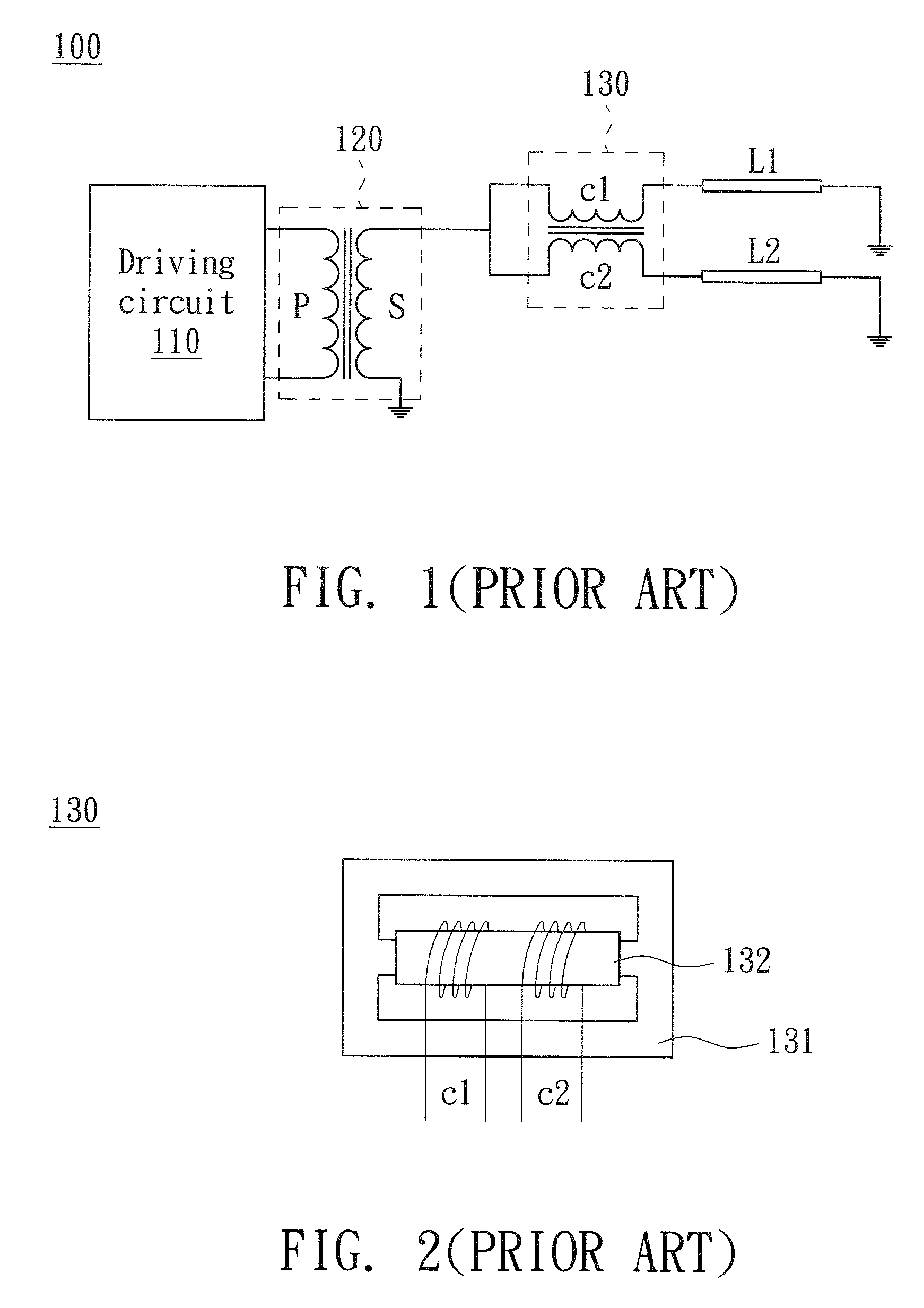
a technology of transformer and driving circuit, applied in the direction of electric variable regulation, process and machine control, instruments, etc., can solve the problems of increasing the number of balancing transformers and circuit complexity, the inability to effectively reduce the cost and time for assembling the multi-lamp driving circuit b>100/b>, and the inability to avoid the condition, etc., to achieve better current balancing control, shorten the time of winding coils, and improve the coupling property
- Summary
- Abstract
- Description
- Claims
- Application Information
AI Technical Summary
Benefits of technology
Problems solved by technology
Method used
Image

Examples
second embodiment
[0044]FIG. 5 is a schematic diagram showing a multi-lamp driving circuit according to a second embodiment of the invention. As shown in FIG. 5, the multi-lamp driving circuit 300 of the embodiment is different from that of FIG. 3 in that the balancing winding set 324 of FIG. 5 further includes a third balancing coil d3 and a fourth balancing coil d4 which wind the core in a combinative way, the first balancing coil d1 (d2) is disposed between the primary winding set 322 and the secondary winding set 323, and the secondary winding set 323 is disposed between the first balancing coil d1 (d2) and the third balancing coil d3 (d4). First ends of the first to fourth balancing coils d1 to d4 are respectively coupled to first ends of the four lamps M1 to M4, second ends of the first to fourth balancing coils d1 to d4 are respectively coupled to two ends of the secondary coil S, and second ends of the lamps M1 to M4 are grounded.
[0045]As mentioned above, the multi-lamp driving circuit 300 of...
third embodiment
[0046]FIG. 6 is a schematic diagram showing a multi-lamp driving circuit according to a third embodiment of the invention. As shown in FIG. 6, the multi-lamp driving circuit 300 of the embodiment is different from that of the first and second embodiments in that the transformer 320 of FIG. 6 adopts a rectangular core 321 in which two bobbins 325(1) and 325(2) are disposed, wherein the primary winding set 322 winds around the bobbin 325(1), and the secondary winding set 323 and the balancing winding set 324 wind around the bobbin 325(2). In addition, the first ends of the first and second balancing coils d1 and d2 are respectively coupled to the first ends of the lamps M1 and M2, the second ends of the lamps M1 and M2 are coupled to the first end of the secondary coil S, and the second ends of the first and second balancing coils d1 and d2 and the secondary coil S are grounded. The secondary winding set 323 is coupled to the balancing winding set 324 through the lamps M1 and M2. As m...
fourth embodiment
[0048]FIG. 8 is a schematic diagram showing a multi-lamp driving circuit according to a fourth embodiment of the invention. As shown in FIG. 8, the multi-lamp driving circuit 300 of the embodiment is different from that of FIG. 6 in that the balancing winding set 324 of FIG. 8 further includes a third balancing coil d3 and a fourth balancing coil d4 which wind around the core in a combinative way, and the secondary winding set 323 is disposed between the first balancing coil d1 (d2) and the third balancing coil d3 (d4). In addition, the first ends of the first to fourth balancing coils d1 to d4 are respectively coupled to the first ends of the lamps M1 to M4, the second ends of the lamps M1 to M4 are respectively coupled to the two ends of the secondary coil S, and the second ends of the first to fourth balancing coils d1 to d4 are grounded. As mentioned hereinabove, it is obtained that the arrangement of the multi-lamp driving circuit 300 of FIG. 8 still can obtain the above-mentio...
PUM
 Abstract
Description
Claims
Application Information
 - R&D
- Intellectual Property
- Life Sciences
- Materials
- Tech Scout
- Unparalleled Data Quality
- Higher Quality Content
- 60% Fewer Hallucinations
Browse by: Latest US Patents, China's latest patents, Technical Efficacy Thesaurus, Application Domain, Technology Topic, Popular Technical Reports.
© 2025 PatSnap. All rights reserved.Legal|Privacy policy|Modern Slavery Act Transparency Statement|Sitemap|About US| Contact US: help@patsnap.com