
Exhaust gas decontamination system and method of exhaust gas decontamination

a decontamination system and exhaust gas technology, applied in mechanical equipment, machines/engines, electric control, etc., can solve the problems of nox purification performance deterioration, catalyst surface increase of co2 /sub>2, and neither the combustion temperature in the engine cylinder nor the temperature of the exhaust gas rise, so as to curb nox purification performance and reduce nox. , the effect of reducing nox

Inactive Publication Date: 2008-11-11
ISUZU MOTORS LTD
View PDF19 Cites 3 Cited by
  • Summary
  • Abstract
  • Description
  • Claims
  • Application Information

AI Technical Summary

Benefits of technology

The system effectively removes NOx released from the occluding substance during regeneration, maintaining high NOx removal efficiency and preventing catalyst surface temperature drops, thus improving NOx purifying performance and curbing fuel efficiency deterioration.

Problems solved by technology

However, in the exhaust gas purifying system of the Laid-Open Japanese Patent Publication 2000-356127, if O2 concentration in the exhaust gas is decreased by a large quantity of EGR, such problems occur that neither the combustion temperature in the engine cylinder nor the temperature of the exhaust gas rises and that inert gases such as CO2 increase on the catalyst surface.
Therefore, another problem of deterioration in the NOx purifying performance appears, that is because the catalyst surface temperature does not rise during the rich-burn accompanied by the EGR leaving the catalyst unactivated and the generated NO2 is released without being removed, although it is necessary to heat the catalyst surface to a high temperature since a large amount of energy is required to reduce NO2 released from the NOx occluding substance to N2.

Method used


Image

  • Exhaust gas decontamination system and method of exhaust gas decontamination
  • Exhaust gas decontamination system and method of exhaust gas decontamination
  • Exhaust gas decontamination system and method of exhaust gas decontamination

Examples


Embodiment Construction

[0050]Now, the exhaust gas purifying system provided with the NOx occlusion reduction type catalyst and the method of exhaust gas purification according to the present invention shall be described referring to the drawings.

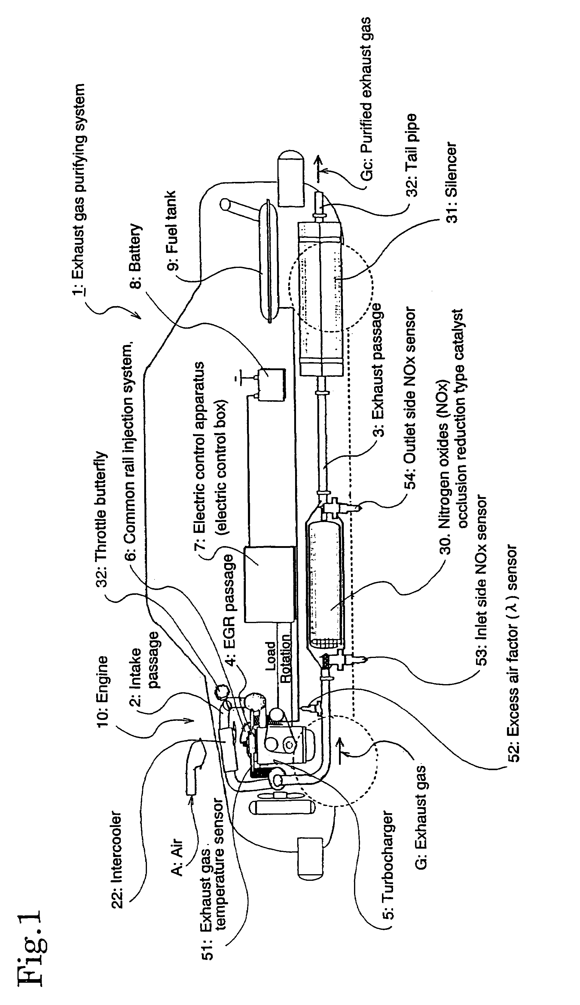
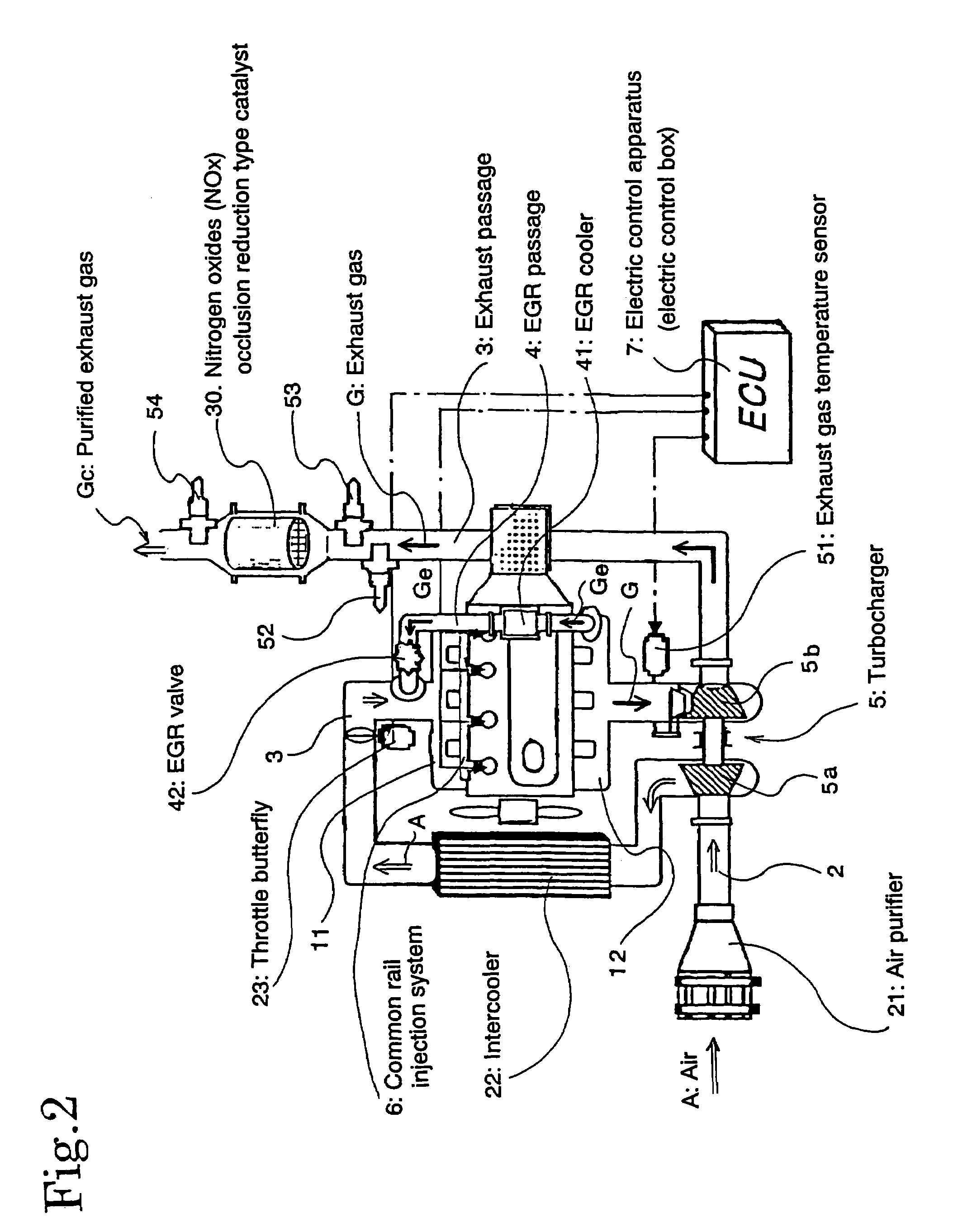
[0051]First, the exhaust gas purifying system 1 provided with the NOx occlusion reduction type catalyst 30 according to the present invention shall be described, referring to FIG. 1 and FIG. 2.

[0052]FIG. 1 shows the composition diagram of an engine 2 and an engine exhaust system of an exhaust gas purifying system 1 provided with a NOx occlusion reduction type catalyst 30 by an example of a diesel engine, while FIG. 2 shows the detail of the engine system part of FIG. 1.

[0053]As shown in FIG. 1 and FIG. 2, in the exhaust gas purifying system 1, an air purifier 21, a compressor 5a of a turbocharger 5, an intercooler 22 and a throttle butterfly (intake throttling valve) 23 are arranged from the upstream side in an intake passage 2 of an engine 10, while an exhaust ga...


PUM


Abstract

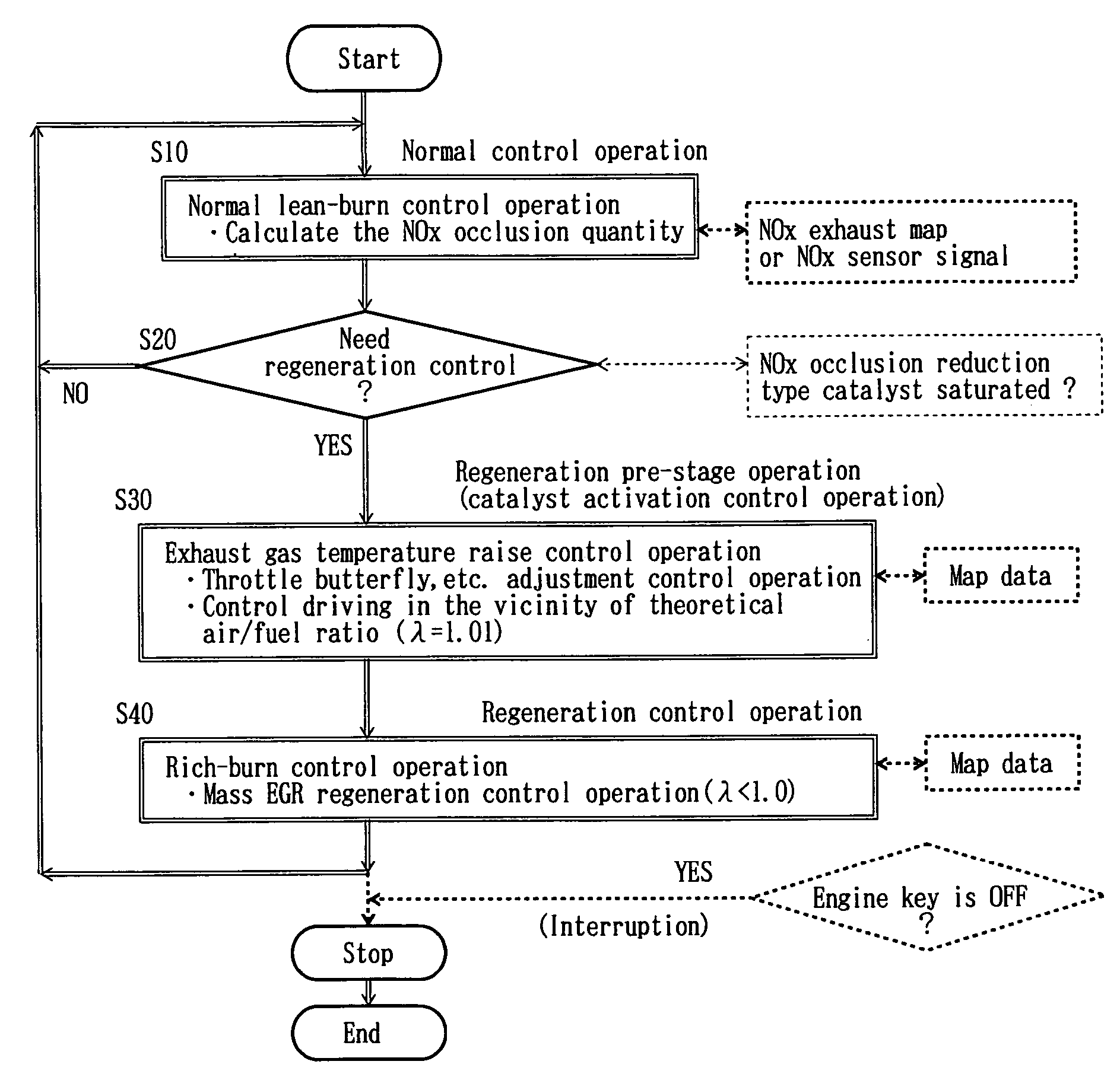
An exhaust gas decontamination system and a method of exhaust gas decontamination wherein in the regeneration of NOx occlusion reduction type catalyst with respect to a lean-burn engine or diesel engine, even in the instance of rich burning accompanied by EGR the NOx released from the NOx occlusion reduction type catalyst can satisfactorily be reduced and purged to thereby exhibit a high NOx removal ratio. The exhaust gas decontamination system (1) provided with the NOx occlusion reduction type catalyst (30) includes a control unit (C1) comprising a.norrnal control operation feature (C10), a regeneration control initiation judging feature (C20), a catalyst activation control-operation feature (C30) and a rich-burn control operation feature (C40) capable of lowering the concentration of oxygen in the exhaust gas so as to realize such a constitution that the catalyst is carried out just before rich burning accompanied by EGR.

Description

TECHNICAL FIELD[0001]The present invention concerns an exhaust gas purifying system for purifying nitrogen oxides in an exhaust gas, provided with a nitrogen oxides occlusion reduction type catalyst in an internal combustion engine such as a diesel engine, and a method of exhaust gas purification.BACKGROUND ART[0002]Various studies and proposals have been made relating to a nitrogen oxides (NOx, hereinafter) catalyst for reducing and removing NOx in an exhaust gas of an internal combustion engine such as a diesel engine and certain gasoline engines or various combustion apparatus.[0003]Among these NOx catalysts, a NOx occlusion reduction type catalyst containing NOx occluding substance is used or under consideration to be used for purifying an exhaust gas from a lean-burn gasoline engine or a diesel engine.[0004]Unlike a three-way-catalyst, this NOx occlusion reduction type catalyst can purify NOx even if oxygen (O2, hereinafter) exists in an exhaust gas. FIG. 9 shows the structure ...

Claims


Application Information

Patent Timeline
Patent Type & Authority Patents(United States)
IPC IPC(8): F02M25/06F01N3/08F01N3/28F02B37/00F02D11/10F02D21/08F02D41/00F02D41/02F02D41/14F02D41/40F02M25/07
CPCF01N3/0814F01N3/0842F01N3/2828F02D41/0002F02D41/0245F02D41/0275F02D41/1441F02D41/146F02D41/402F02M25/0707F02M25/0727F01N2560/026F02B29/0406F02B37/00F02D11/105F02D41/0055F02D2200/0806F02D2250/18F02M25/0718Y02T10/44Y02T10/26Y02T10/42F02M26/05F02M26/15F02M26/23Y02T10/12Y02T10/40
Inventor GABE, MASASHINAGAOKA, DAIJI
Owner ISUZU MOTORS LTD
Learn More