
Exhaust gas purification catalyst

a technology of exhaust gas and purification catalyst, which is applied in the direction of physical/chemical process catalysts, other chemical processes, separation processes, etc., can solve the problems of deterioration of heat transfer from exhaust gas to lower layer, delay in temperature rise of lower layer, and insufficient improvement of exhaust gas purification performance by gas diffusion, etc., to prevent deterioration of pd catalyst, enhance durability of catalytic converter, and enhance catalytic reaction

Inactive Publication Date: 2008-11-04
MAZDA MOTOR CORP
View PDF13 Cites 20 Cited by
  • Summary
  • Abstract
  • Description
  • Claims
  • Application Information

AI Technical Summary

Benefits of technology

[0008]According to the first aspect of the invention, the upper catalytic layer directly receives heat from exhaust gas to quickly activate the catalytic material loaded on the upper layer. Simultaneously, the lower layer functions to prevent heat transfer to the carrier because of the thermal insulation effect of the hollow oxide powder. Eventually both of the functions may result advantageously in the improvement of low temperature activation of the catalytic converter as a whole.
[0012]According to the second aspect of the invention, since the upstream end region of the catalytic converter first receives heat from the exhaust gas flowing through the exhaust gas passage and the hollow oxide powder is provided in the upstream lower layer which is within the predetermined range from the upstream end in the exhaust gas flow direction, catalytic activity at the upstream lower layer is excited and maintained by heat from exhaust gas and its catalytic reaction and the region showing activity with effect of the catalytic heat is spreading downstream as the exhaust gas flows. At the same time, the invention reduces use of hollow oxide powder by using it only for the upstream lower layer, which results on cost reduction while enhancing the light off performance. The range of lower layer with the hollow oxide powder may be only the proximity of the upstream end of the carrier, a range from the upstream end to a center part of the carrier in the direction of exhaust gas flow, or a range from the upstream end beyond the center part to a downstream side.
[0015]In another embodiment of the present invention, the hollow oxide powder in the lower layer may carry precious metal such as Pt or Pd as the catalytic metal. Also, the solid oxide powder in the upper layer may carry precious metal such as Rh. In a case that the solid oxide powder carries Rh in the upper layer, the Rh catalyst in the upper layer promotes steam reforming reaction or partial oxidizing reaction of hydrocarbon in the exhaust gas to cause it to become more active decomposed product such as H2 and partially oxidized hydrocarbon, which is provided to the lower layer to enhance catalytic reaction therein. Since that decomposed product of hydrocarbon is smaller in size compared to the original hydrocarbon, it can more easily pass through the shell wall of the hollow oxide powder in the lower layer so as to take advantage of gas diffusion in the larger porous volume of the hollow oxide powder than that of the solid oxide powder. Further in a case that the Pd catalyst is loaded on the lower layer, the hydrocarbon, which might poison Pd, is purified or converted to more reactive partly oxidized hydrocarbon at the upper layer, which may prevent deterioration of the Pd catalyst in the lower layer so as to enhance durability of the catalytic converter.
[0016]Further in the above embodiment, when Pt catalyst is loaded on the solid oxide powder of the upper layer in addition to the Rh catalyst, oxidizing reaction of high molecular hydrocarbon may be promoted at the upper layer by the Pt catalyst so as to improve exhaust gas purification performance of the catalytic converter. The Pt catalyst may also increase the production of partly oxidized hydrocarbon at the upper layer so as to enhance the reactivity of exhaust gas at the lower layer while preventing the HC poisoning of the Pd catalyst in the lower layer as described above. Further the Pt catalyst in the upper layer may promote oxidizing reaction of hydrocarbon as described above to form local reducing atmosphere which may prevent oxidization of the Rh catalyst in the upper layer, that might deteriorate its catalytic reactivity in oxidizing atmosphere.

Problems solved by technology

Accordingly, when exhaust gas pressure is low, e.g. in an engine idle condition just after engine start, the improvement of exhaust gas purification performance by the gas diffusion can not be obtained enough.
Especially, in a cold engine start condition, the hollow oxide powder contained in the upper layer of catalyst functions as a heat insulator, thereby heat transfer from the exhaust gas to the lower layer is deteriorated, and, also since heat is deprived further from the lower layer to the honeycomb-shaped carrier, temperature rise of the lower layer is delayed which is a disadvantage in terms of activation of catalyst in cold start condition (light-off performance).

Method used


Image

  • Exhaust gas purification catalyst
  • Exhaust gas purification catalyst
  • Exhaust gas purification catalyst

Examples


Embodiment Construction

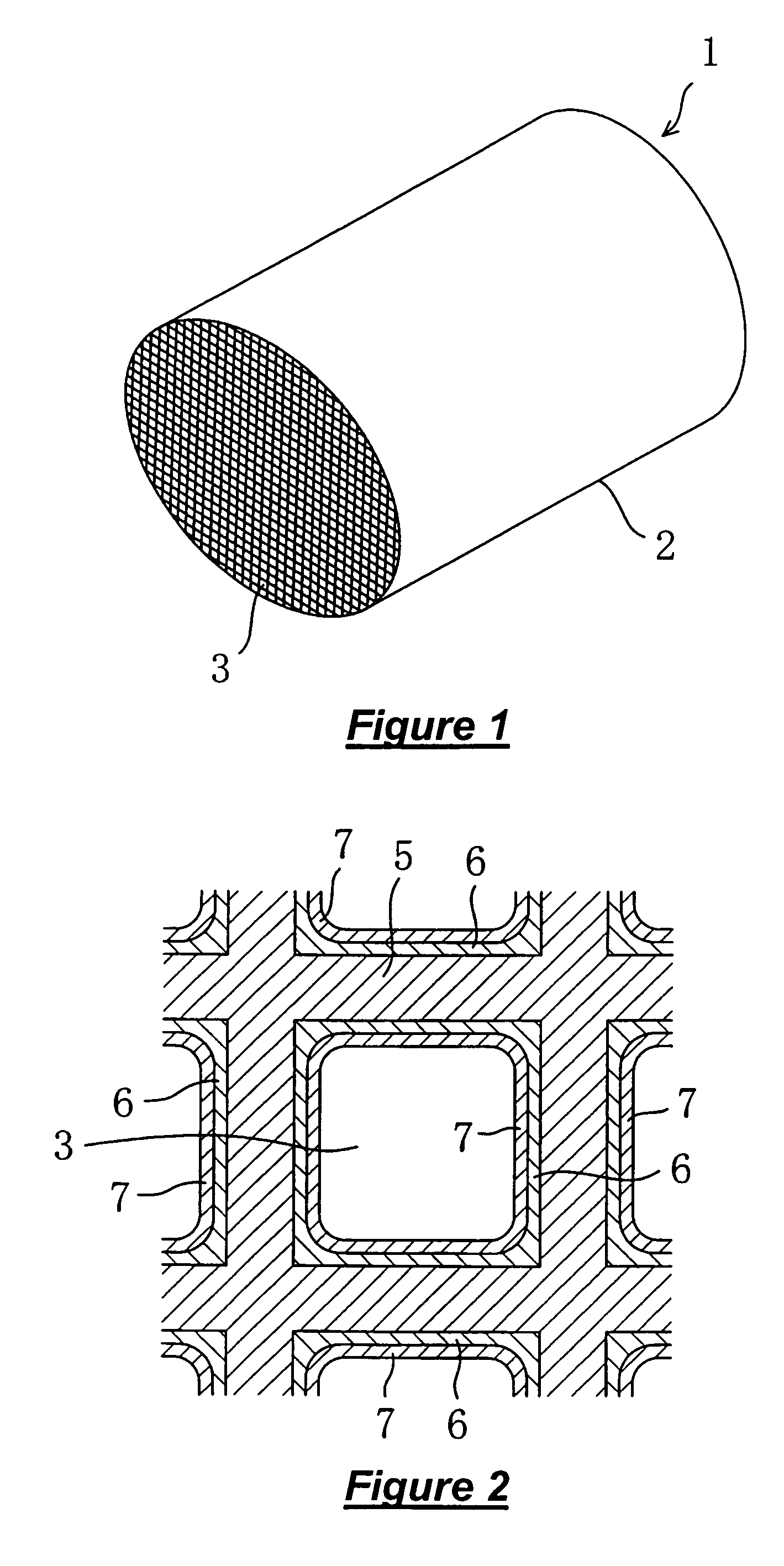
[0022]FIG. 1 shows catalytic converter for exhaust gas purification (three way catalyst) 1 arranged in an exhaust gas passage from an internal combustion engine of an automotive vehicle. The catalytic converter 1 has porous a monolith carrier 2 having a honeycomb shaped cross section comprising a number of cells 3 forming exhaust gas passages.

[0023]With reference to FIG. 2, catalytic layers are shown to be coated on surfaces of cell walls 5 of the carrier cells 3. The catalytic layers have a dual layer structure with a lower layer 6 coated directly over the cell walls 5 and an upper layer 7 coated over the lower layer 6 and directly exposed to exhaust gas flowing in the cell (exhaust gas passage) 3.

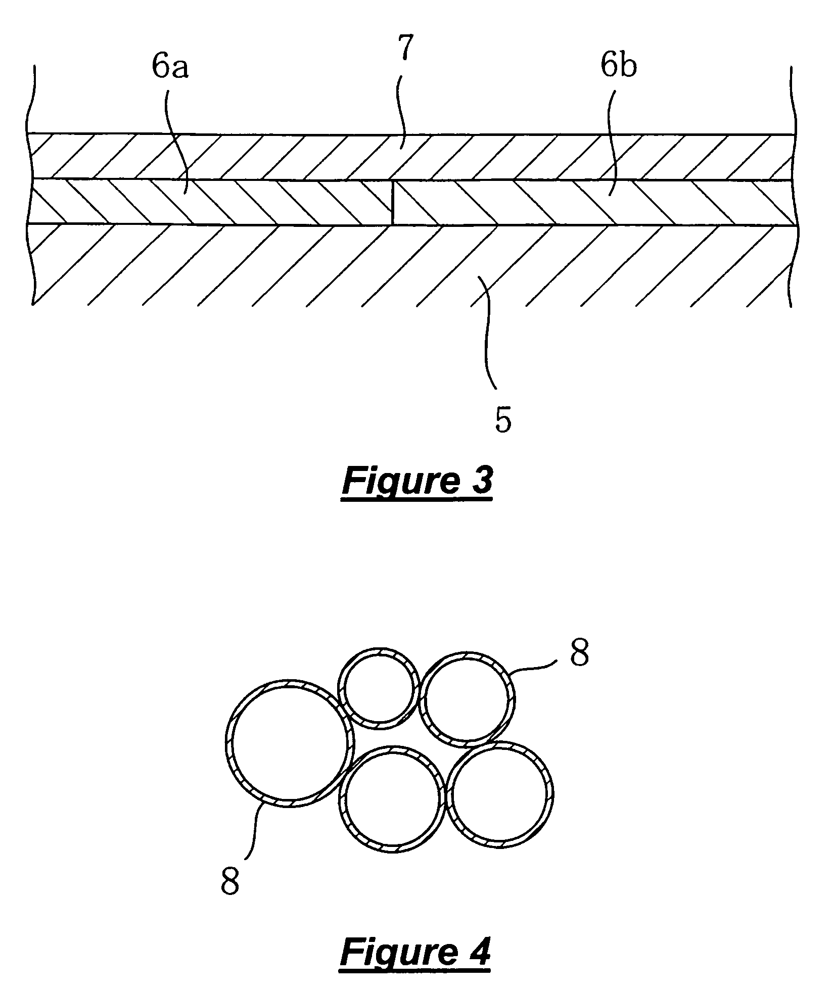
[0024]The lower layer 6 contains ceria or alumina based hollow oxide powder loaded with catalytic metal. On the other hand, the upper layer 7 contains solid oxide powder loaded with catalytic metal. The lower layer may contain, in addition to the hollow oxide powder, solid oxide powder lo...


PUM

PropertyMeasurementUnit
temperatureaaaaaaaaaa
frequencyaaaaaaaaaa

Abstract

Catalytic converter comprises a carrier having exhaust gas passages therein, a lower catalytic layer coated over the carrier and comprising hollow oxide powder loaded with catalytic metal, and an upper catalytic layer coated over the lower catalytic layer, directly exposed to exhaust gas flowing in the exhaust gas passages and comprising solid oxide powder loaded with catalytic metal. The hollow oxide powder may be ceria or alumina base oxide. Further it may be mixed oxide such as Ce—Zr mixed oxide or La contained alumina as well.

Description

BACKGROUND OF THE INVENTION[0001]This invention relates to an exhaust gas purification catalyst, more particularly to usage of hollow oxide powder for a catalytic layer.[0002]As the catalyst for purifying exhaust gas from an internal combustion engine, it is common to use precious metals such as Pt, Pd or Rh which is loaded on oxide powder such as alumina that is referred to as support material. Alternatively ceria may be adopted as the support material as well considering its oxygen storage capacity. Further, catalytic layers having the support materials may consist of two layers as shown in U.S. Pat. No. 5,019,546 or Japanese Patent Application Publication no. S63-258648.[0003]It is also known to use hollow oxide powder as the support material in order to enhance catalyst performance as shown in Japanese Patent Application Publication nos. 2000-203830 or 2001-347167. By using the hollow oxide powder as support material, porous volume of the catalytic layer is increased thereby enh...

Claims


Application Information

Patent Timeline
Patent Type & Authority Patents(United States)
IPC IPC(8): B01J23/00B01J20/00B01J21/00
CPCB01D53/945B01J23/40B01J23/63B01J35/04B01J35/10B01J37/0232B01J37/0244B01J37/0248Y02T10/22Y02T10/12
Inventor MIYOSHI, SEIJITAKAMI, AKIHIDEYAMADA, HIROSHIAKAMINE, MASAAKIIWAKUNI, HIDEHARUHARADA, KOICHIRO
Owner MAZDA MOTOR CORP
Learn More