Nanoelectrochemical cell

a technology of nanoelectrochemical cells and nanoelectrochemical electrodes, which is applied in the direction of capacitor details, capacitor dielectric layers, solid-state devices, etc., can solve the problems of reducing the overall surface area of the nanoelectrochemical electrodes. , to achieve the effect of improving the electrochemical performance and

Inactive Publication Date: 2008-11-04
SHARP KK
View PDF7 Cites 6 Cited by
  • Summary
  • Abstract
  • Description
  • Claims
  • Application Information

AI Technical Summary

Benefits of technology

[0007]Accordingly, a method is provided for forming a NanoElectroChemical (NEC) cell. The method provides a bottom electrode with a top surface. Nanowire shells are formed. Each nanowire shell has a nanowire and a sleeve, with the nanowire connected to the bottom electrode top surface and the sleeve (optionally) covering a nanowire tip. A top electrode is formed overlying the nanowire shells. A main cavity is formed between the top electrode and bottom electrodes, partially displaced by a first plurality of nanowire shells. A support column, approximately centered under the top electrode, also helps to define the main cavity.

Problems solved by technology

However, the relatively fine structure of individual nanowires is necessarily more prone to breakage and physical damage.
Nanowires are an ineffective means of interlevel mechanical support.
But the fill between nanowires reduces the overall surface area of the nanowire electrode.

Method used


Image

  • Nanoelectrochemical cell
  • Nanoelectrochemical cell
  • Nanoelectrochemical cell

Examples


Embodiment Construction

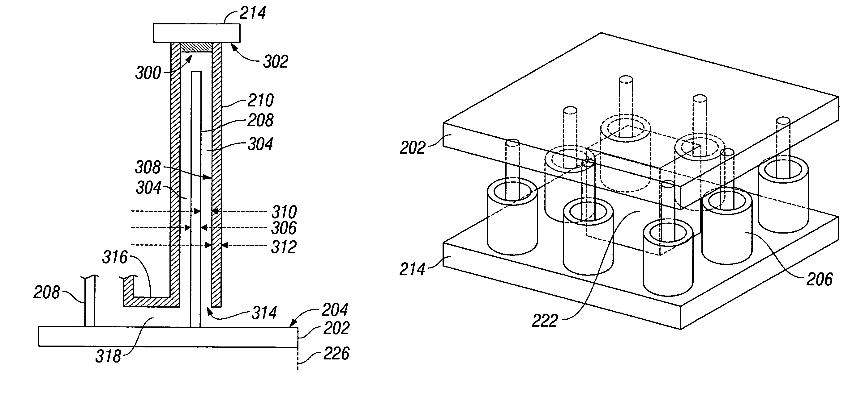
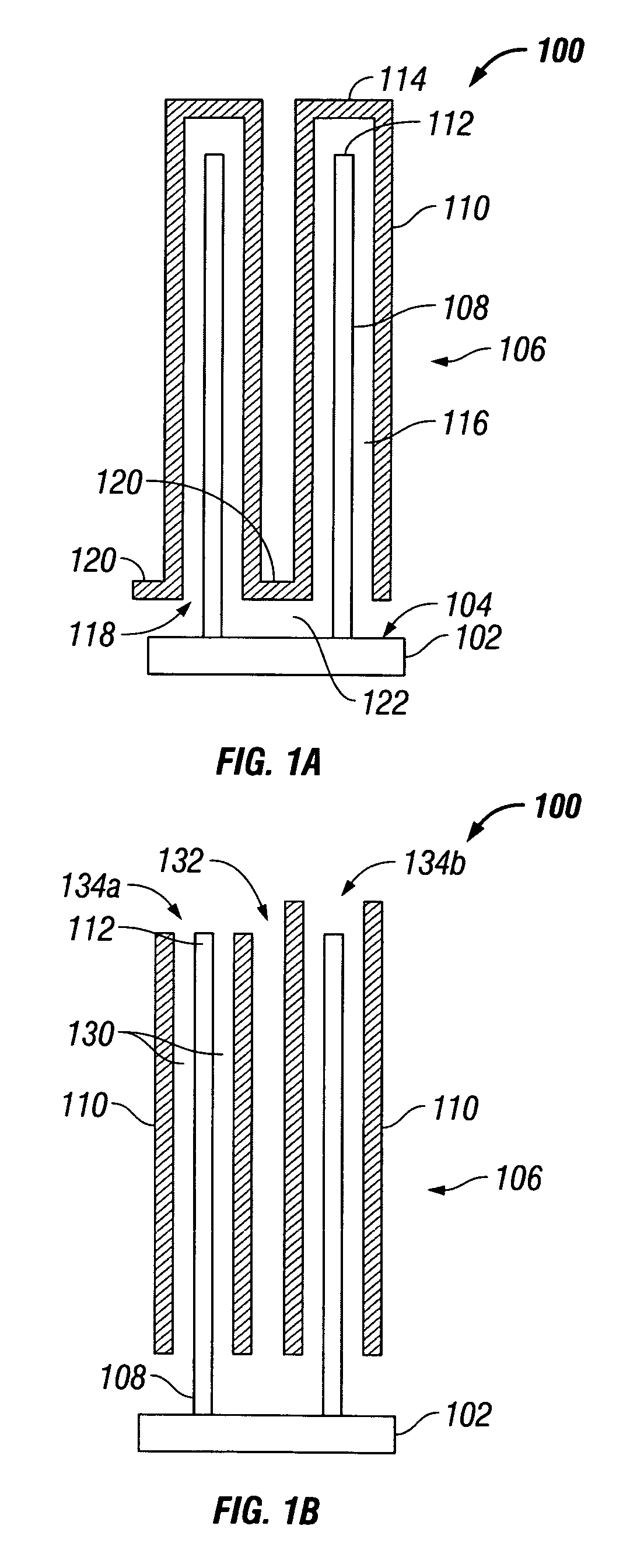
[0017]FIGS. 1A and 1B are partial cross-sectional views of a nanowire support structure. In FIG. 1A, the support structure 100 comprises a bottom substrate 102 with a top surface 104. A plurality of nanowire shells 106 is shown. Each nanowire shell 106 has a nanowire 108 and a sleeve 110. The nanowire 108, which may alternately be referred to as a nanostructure or nanorod, is connected to the bottom substrate top surface 104, and the sleeve 110 may cover a nanowire tip 112 with a lid 114, as shown. Sleeve cavities 116 are interposed between each sleeve 110 and nanowire 108. In some aspects, the bottom substrate 102 and nanowires 108 are made from a conductive material and may function as an electrode. However, in other aspects, nonconductive materials may be used.

[0018]Each sleeve 110 also has a sleeve bottom opening 118. A shell coating layer 120 overlies the, bottom substrate top surface 104 and joins the plurality of sleeve openings 118. A surface cavity 122 is interposed between...


PUM

PropertyMeasurementUnit
diameteraaaaaaaaaa
diameteraaaaaaaaaa
thicknessaaaaaaaaaa

Abstract

A method is provided for forming a NanoElectroChemical (NEC) cell. The method provides a bottom electrode with a top surface. Nanowire shells are formed. Each nanowire shell has a nanowire and a sleeve, with the nanowire connected to the bottom electrode top surface. A top electrode is formed overlying the nanowire shells. A main cavity is formed between the top electrode and bottom electrodes, partially displaced by a first plurality of nanowire shells. Electrolyte cavities are formed between the sleeves and nanowires by etching the first sacrificial layer. In one aspect, electrolyte cavities are formed between the bottom electrode top surface and a shell coating layer joining the sleeve bottom openings. Then, the main and electrolyte cavities are filled with either a liquid or gas phase electrolyte. In a different aspect, the first sacrificial layer is a solid phase electrolyte that is not etched away.

Description

BACKGROUND OF THE INVENTION[0001]1. Field of the Invention[0002]This invention generally relates to integrated circuit (IC) and semiconductor processes and, more particularly, to a NanoElectroChemical (NEC) cell and associated fabrication process.[0003]2. Description of the Related Art[0004]Nanowire structure electrodes are being incorporated into a number of thin-film electrical devices. The combination of many nanowires attached to an electrode provides a larger overall surface area than a conventional flat-surface electrode, improving electrical performance. However, the relatively fine structure of individual nanowires is necessarily more prone to breakage and physical damage. Nanowires are an ineffective means of interlevel mechanical support. One method of improving mechanical interlevel support is to fill the space surrounding the nanowires with dielectric, leaving just the nanowire tips exposed. But the fill between nanowires reduces the overall surface area of the nanowire ...

Claims


Application Information

Patent Timeline
Patent Type & Authority Patents(United States)
IPC IPC(8): H01L21/20
CPCH01G9/07Y10T29/417Y10S977/762
Inventor ZHANG, FENGYANEVANS, DAVID R.HSU, SHENG TENG
Owner SHARP KK
Why Eureka
Try Eureka