
Golf club head

a golf club and club head technology, applied in the field of golf club heads, can solve the problems of poor stability (accuracy) of the direction of the ball hit, inferior related techniques, and easy damage to the clubface, and achieve the effect of improving the directional stability of the ball hi

Inactive Publication Date: 2008-11-04
DAIWA SEIKO CORPORATION
View PDF15 Cites 65 Cited by
  • Summary
  • Abstract
  • Description
  • Claims
  • Application Information

AI Technical Summary

Benefits of technology

[0020]The invention was made based on the problems, and an object of the invention is to provide a golf club head which can stabilize the swing of a golf club to thereby realize the improvement in directional stability of a ball hit.
[0021]In addition, another object of the invention is to provide a golf club head in which a member having a higher specific strength than that of a head body is mounted in a crown portion of the head body so as not only to realize the lowering the center of gravity of the head but also to effectively reinforce the crown portion to thereby realize the improvement in the repulsion properties of a face portion.
[0022]Furthermore, a further object of the invention is to provide a golf club head which enables the weight adjustment of a head body with ease and good accuracy.

Problems solved by technology

Thus, with the related techniques, there is caused a problem that the techniques are inferior in an aspect of orienting the clubface square to the ball.
As a result, in the related techniques, the swing tends to be easily destabilized during the path indicated by the arrow D due to the operation for controlling the inertial force generated by the weight component which is caused to reside at the single point in the head, and a certain swing technique is required to cope with the inertial force so generated so as to orient the clubface square to the ball, thus leading to a problem that the related techniques are inferior with respect to the stability (accuracy) of the direction of the ball hit.
In the case that the thickness of the clubface is decreased or changed, however, there is caused a problem that the clubface becomes easier to be damaged as the thickness thereof is decreased or changed.
Since the golf club head disclosed in Patent Document 3 is constructed such that the whole of the crown portion is deflected, the energy generated at impact is transmitted to the rear of the crown portion in association with the deflection, and hence the energy is lost, whereby the properties of reaction become difficult to be improved, leading to a problem that the driving distance cannot be improved sufficiently.
In addition, while the golf club head disclosed in Patent Document 4 can realize the lowering of the center of gravity by using the fiber-reinforced resin plate having the high specific strength, as with the construction disclosed in Patent Document 1, since the entirety of the crown portion is deflected, the loss of energy is caused, leading to the problem that the driving distance cannot be improved sufficiently.
Furthermore, there is caused another problem that due to too small the hitting sound and too soft the hitting feeling, a hitting error becomes difficult to be sensed by the player.
The golf club head disclosed in Patent Document 5 is formed so as to adopt the technique to adjust the overall weight of the head and however has a problem that the position of the center of gravity thereof is difficult to be adjusted (a slight vertical weight adjustment is possible).
In addition, as to the golf club head disclosed in Patent Document 6, while the overall weight of the head can be adjusted, the position of the center of gravity thereof is difficult to be adjusted, and there is possibly caused a risk that the external shape is changed depending upon the amount of abrasion, whereby the external appearance is defaced.

Method used


Image

  • Golf club head
  • Golf club head
  • Golf club head

Examples


first embodiment

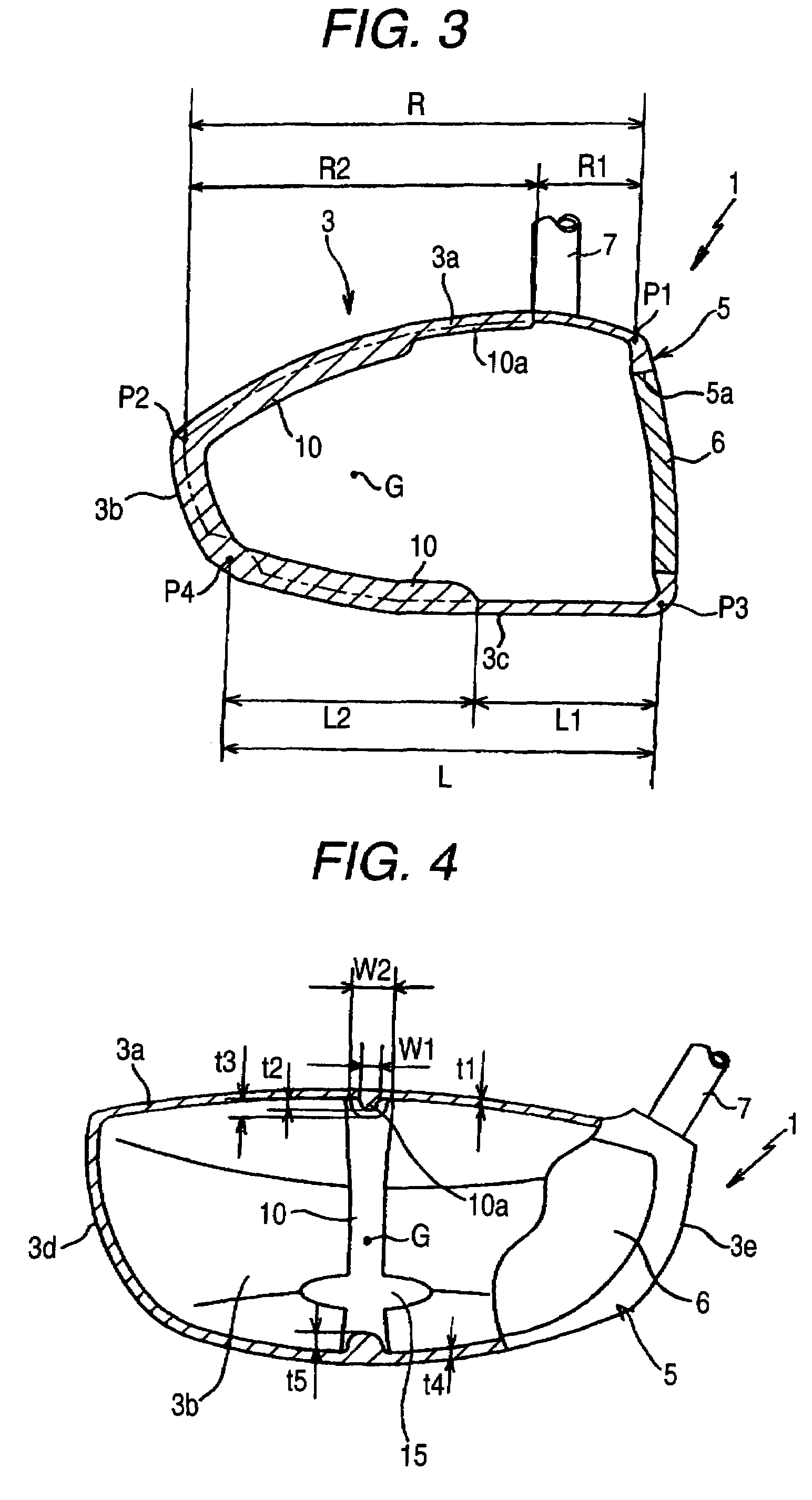
[0079]FIGS. 3 to 6 show a golf club head according to a first embodiment of the invention, in which FIG. 3 is a longitudinal sectional view taken along a line passing through a position where the center of gravity of a head exists, FIG. 4 is a transverse sectional view taken on a face side of the head, FIG. 5 is a plan view of the head, and FIG. 6 is a bottom view of the head.

[0080]A head body 1 of a golf club head (hereinafter, referred to as a head) according to the first embodiment includes a rear member 3 which is made up, in turn, of a crown portion 3a, a back portion 3b, a sole portion 3c, a toe portion 3d and a heal portion 3e, and a front member (a face portion) 5 which is welded to or integrated into the rear member 3. Then, an opening 5a is formed in the face portion 5, and a face member 6 is securely held in the opening via welding, press fitting or bonding, whereby the head body 1 is constructed into a hollow shell structure.

[0081]Note that all of the shell members of th...

second embodiment

[0095]FIGS. 8 and 9 are such as to illustrate a second embodiment of the invention, in which FIG. 8 is a longitudinal sectional view of a golf club head taken along the line which passes through the center of gravity of the head and FIG. 9 is a plan view of the head.

[0096]In the embodiment that has been described before, while the weight-massed portion 10 is formed in such a manner as to extend continuously from the crown portion 3a to the sole portion 3c of the head body 1, a weight-massed portion 30, which extends in the face-to-back direction as shown in the drawings, may be formed only on a crown portion 3a. Namely, in heads of a hollow construction, in general, the sole portion tends to be made relatively heavy with a view to realizing a low center of gravity, and the crown portion tends to be formed relatively thin due to no adjustment being made for the center of gravity. Due to this, by forming the weight-massed portion 30 on the crown portion which constitutes the thin port...

third embodiment

[0097]FIGS. 10 and 11 are such as to illustrate a third embodiment of the invention, in which FIG. 10 is a plan view of a golf club head and FIG. 11 is a bottom view of the head.

[0098]While in the embodiments that have been described before, the weight-massed portions are formed in the direction normal to the face portion of the head, a weight-massed portion 40 according to this embodiment is formed in such a manner as to curve along the swing plane when a head body 1 is seen from the top. Namely, by forming the weight-massed portion 40 in such a manner as to so curve, the effect to make the shaft rotation follow the direction of the swing plane can be increased further, whereby the swing is made difficult to deflect and stable. In particular, an effect to make the turn of the head follow the direction of the swing plane is increased to thereby facilitate the shot of a draw ball (a ball path which slightly curves from the right to the left). As this occurs, in the event that a weigh...


PUM


Abstract

A golf club head includes: a hollow shell head body that defines a face portion for hitting a ball and a crown portion; and a weight-massed portion that is formed on at least crown portion, wherein the weight-massed portion extends in a face-to-back direction of the head body and has a larger mass than that of a peripheral portion of the head body.

Description

BACKGROUND OF THE INVENTION[0001]The present invention relates to a golf club head.[0002]Generally, there has been known a golf club head in which a weight body is disposed in the interior of a hollow head in order to improve the directionality of a golf ball hit by the head. For example, in Patent Document 1, a golf club head is disclosed in which a weight body is placed at a position located at the rear of a crown portion and close to the axis of a club shaft in order to set the angle of the center of gravity of the head within a predetermined range (30.5 to 35 degrees). According to the golf club head like this, since a face side is made to rotate easily about the axis of the club shaft when a golf club is swung, the head is also made to easily turn, thereby making it possible to obtain an effect to prevent a slice shot. In addition, in Patent Document 2, a golf club head is disclosed in which a weight body is placed on a face side in the vicinity of a sweet spot. According to th...

Claims


Application Information

Patent Timeline
Patent Type & Authority Patents(United States)
IPC IPC(8): A63B53/04
CPCA63B53/0466A63B2053/0416A63B2053/045A63B2209/02A63B2053/0491A63B53/045A63B53/0416A63B60/02
Inventor KUSUMOTO, HARUNOBU
Owner DAIWA SEIKO CORPORATION
Learn More