
Slit lamp table

a lamp table and lamp body technology, applied in the field of tables, can solve the problems of inaccurate testing, unfavorable slit lamp table, and unsuitable prior art slit lamp tabl

Active Publication Date: 2008-11-04
BEATTIE BRIAN
View PDF7 Cites 9 Cited by
  • Summary
  • Abstract
  • Description
  • Claims
  • Application Information

AI Technical Summary

Benefits of technology

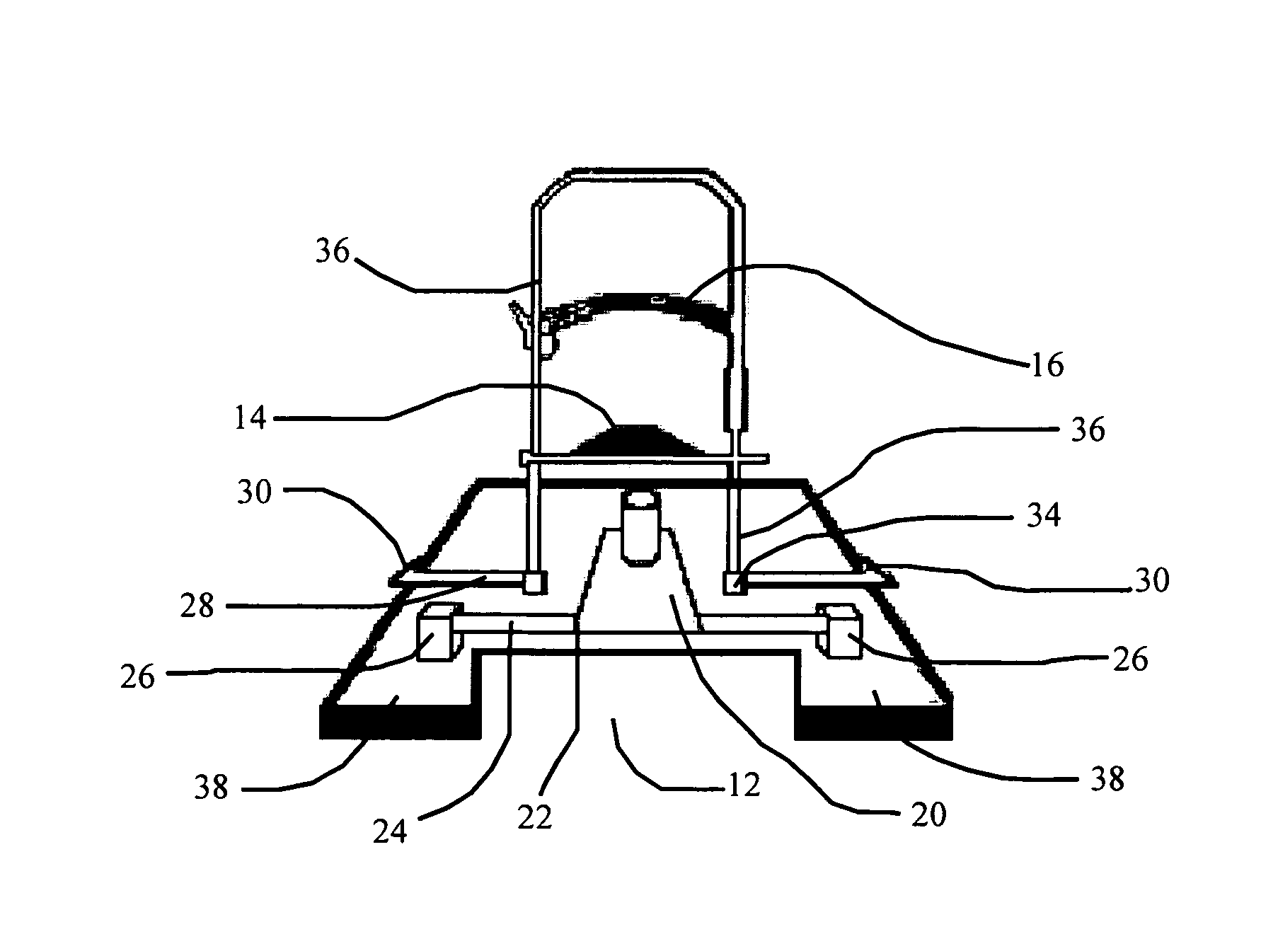
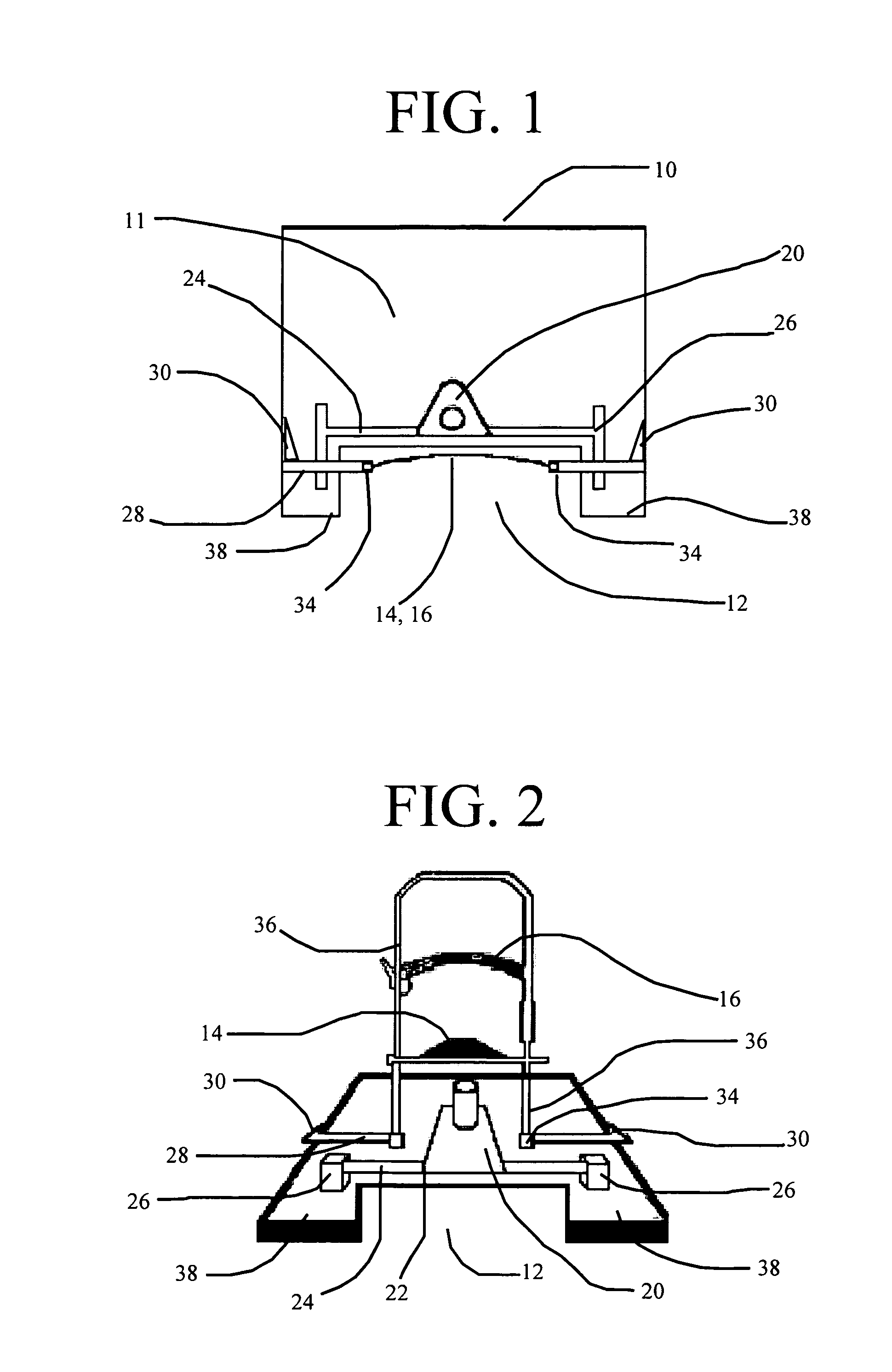
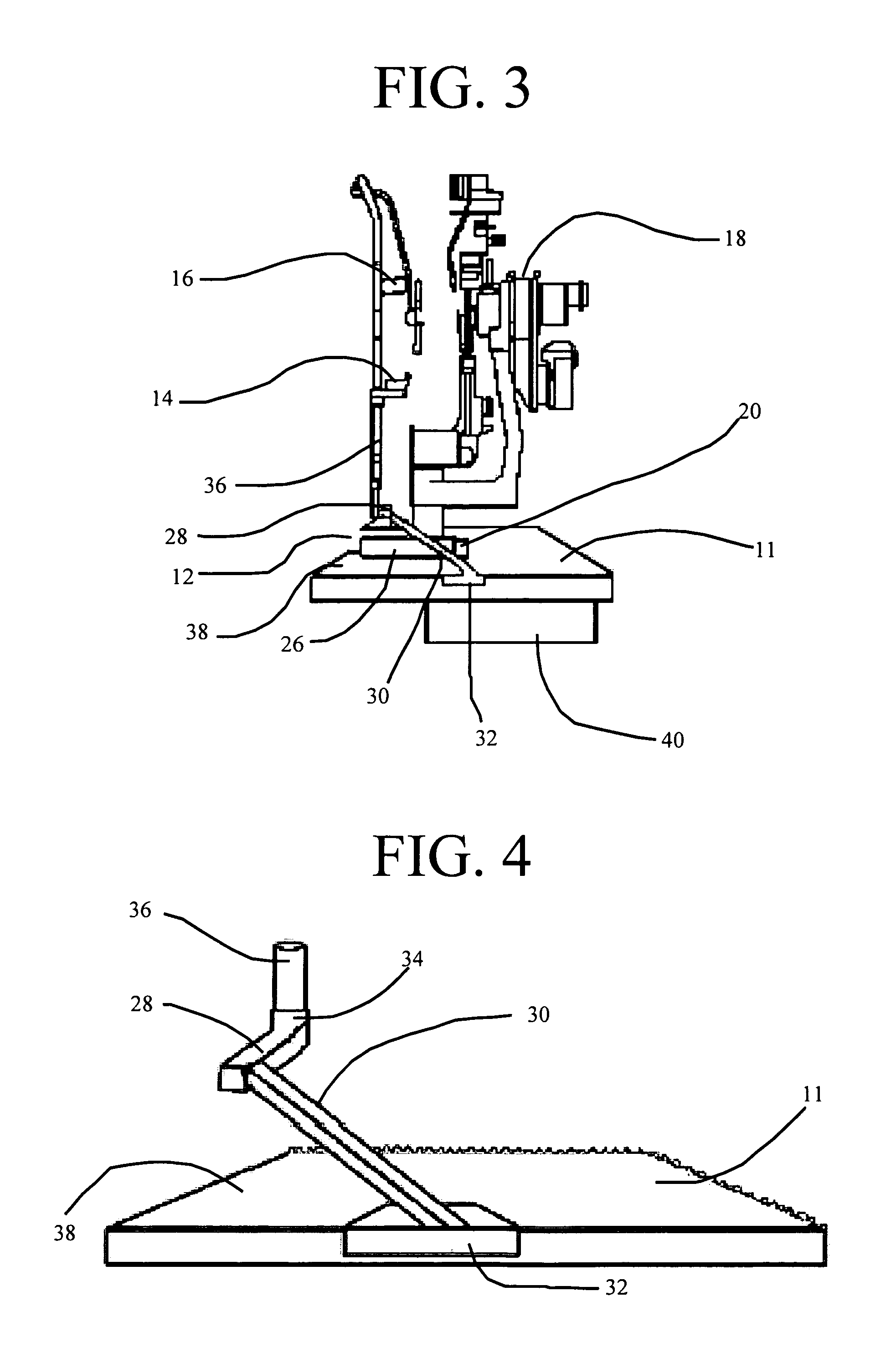
[0010]The present invention provides a new and improved table for a slit lamp microscope having a centrally located recess or opening at the front end edge to receive the torso of the patient having his or her eyes examined. The present invention further provides a means for locating the chin and forehead supports above the opening. The fixture containing the chin and head supports is supported through a pair of angled brackets attached to the sides of the table so as not to interfere with the centrally located opening.
[0013]The present invention allows an individual confined to a wheel chair or an obese individual to move his or her torso closer to the slit lamp microscope thereby placing the individuals head closer to the slit lamp microscope resulting in the proper placement of the patients chin and forehead on the chin and forehead supports to ensure accurate testing or treatment results.

Problems solved by technology

The prior art slit lamp table is not conducive, and causes difficulties, when using a slit lamp microscope to examine the eyes of an individual in a wheel chair or an overweight individual.
For such people the prior art slit lamp table is quite unsuitable because the rectangular nature of the prior art slit lamp table makes it difficult for an individual confined to a wheel chair to get close enough to the slit lamp microscope to properly rest his or her chin on the chin support and his or her forehead on the forehead support.
The inability of the wheel chair confined individual to properly rest his or her chin and forehead on the supports could result in inaccurate testing results or the inability to test the individual's eyes.
Likewise, an overweight or obese person is limited in his or her ability to get close enough to the slit lamp microscope to properly place his or her chin and forehead in the chin and forehead supports due to the rectangular nature of the prior art tables holding the slit lamp microscope.

Method used


Image

  • Slit lamp table
  • Slit lamp table
  • Slit lamp table

Examples


Embodiment Construction

[0022]Before explaining the disclosed embodiment of the present invention in detail it is to be understood that the invention is not limited in its application since the invention is capable of other embodiments. Also, the terminology used herein is for the purpose of description and not of limitation.

[0023]The apparatus of the invention is schematically illustrated in FIGS. 1, 2 and 3, in which a slit lamp table 10 is illustrated having a centrally located front recess 12, a chin support 14, a forehead support 16 and a movable slit lamp microscope 18. A variety of means can be utilized to support and adjust the table to accommodate the particular person whose eyes are being examined or treated. The preferred method for supporting the table would include a support base located to the side of the table with a pivoting arm (not shown) attached to the bottom side of the table.

[0024]The slit lamp table 10 is a generally planar narrow elongated panel 11 having a top side, a bottom side, ...


PUM


Abstract

A new and improved slit lamp microscope table with a front recess of suitable size to accommodate the torso of the occupant of a wheel chair or an obese individual. With the table set at an appropriate elevation, the handicapped individual can move his or her wheel chair to the vicinity of the table. The wheel chair is rolled toward the table until the user is located with his or her torso in the recess. Once the patient is in position, the table can be lowered to the point at which the arm rests of the table come into contact with the arms on the wheel chair and more positively hold the table and wheel chair in the desired relation.

Description

FIELD OF THE INVENTION[0001]This invention relates to a table for the placement of a slit lamp microscope, laser or similar instrument and more particularly to a table for a slit lamp microscope, laser or similar instrument with the front surface being concave to receive the torso of a person seated at the table having his or her eyes examined or treated.BACKGROUND OF THE INVENTION[0002]A variety of tables for supporting a slit lamp microscope and other eye examination and treatment instruments have been developed over the years and are known in the art. In the prior art, a slit lamp assembly generally included a base with a generally vertical upstanding standard and a table. Conventionally, the upstanding standard includes means to adjust the table height, which may be pneumatic or, in a simple form, a pair of telescoping tubes with a pin to maintain an adjusted height. In any event, means are provided to adjust the table to accommodate the particular individual whose eyes are bein...

Claims


Application Information

Patent Timeline
IPC IPC(8): A61B3/10
CPCA61B3/135
Inventor BEATTIE, BRIAN
Owner BEATTIE BRIAN
Learn More