
Closing system for a door, lid or the like, particularly those of vehicles

a technology for closing systems and doors, which is applied in the field of locking systems, can solve the problems of large space required for the installation of electrodes in the handle, short supply, and additional manual operation, and achieve the effect of easy and inexpensive production

Inactive Publication Date: 2008-11-04
HUF HULSBECK & FURST GMBH & CO KG
View PDF10 Cites 27 Cited by
  • Summary
  • Abstract
  • Description
  • Claims
  • Application Information

AI Technical Summary

Benefits of technology

[0006]The invention is based on the task of developing a reliable lock system of the type cited above which is compact and which can be produced easily and inexpensively
[0008]The hinges make it possible to produce the individual circuit board parts easily, because they are in the flat, spread-out position during the production process. In this phase, the circuit board parts extend over a large area, as a result of which the two electrodes and the shielding can be produced without interference from each other. These components can therefore be manufactured inexpensively and conveniently. For use in the handle, however, the circuit board parts are folded over onto each other and thus made into a compact, collapsed unit. A folded-up, three-layer product with a small base surface is obtained. The space-saving, compact folded product thus obtained can be easily installed in the limited space available in the interior of the handle. The design also allows fast and easy installation.

Problems solved by technology

An additional manual operation is thus required, which is burdensome.
This occupies space in the area of the handle, space which is already in short supply.
This means that a large amount of space is required to install the electrodes in the handle.
The production of such multilayer circuit boards, however, is expensive and time-consuming.

Method used


Image

  • Closing system for a door, lid or the like, particularly those of vehicles
  • Closing system for a door, lid or the like, particularly those of vehicles
  • Closing system for a door, lid or the like, particularly those of vehicles

Examples


Embodiment Construction

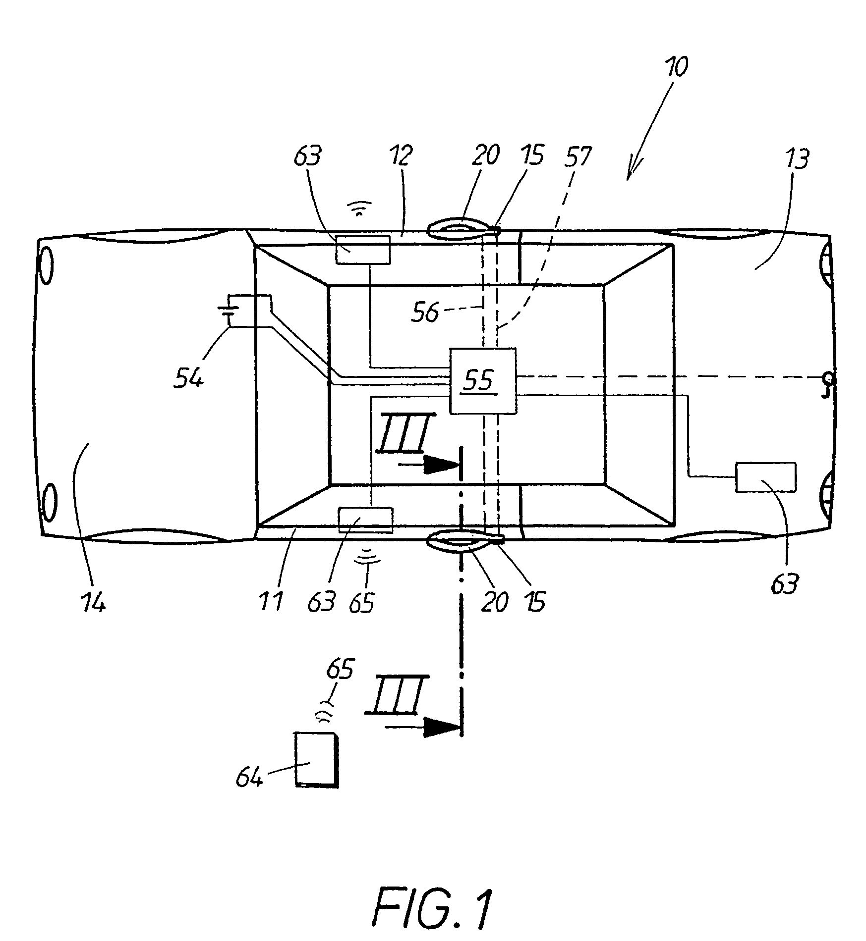
[0020]The lock system according to the invention not only saves a great deal of space but also makes it possible for the authorized user to gain access to the vehicle 10 in an especially quick and convenient manner while also reliably preventing unauthorized third parties from doing the same. In the exemplary embodiment shown, access to the vehicle is possible through two doors 11, 12, through a hatch 13, and through a hood 14. All these movable parts 11-14 are held in their locked positions on the body by the same or different locks 15. The locks can be switched jointly between their locking positions and their release positions by means of a known central control unit. It is sufficient to explain this in greater detail on the basis of one of the handles 20, belonging to one of the doors 11.

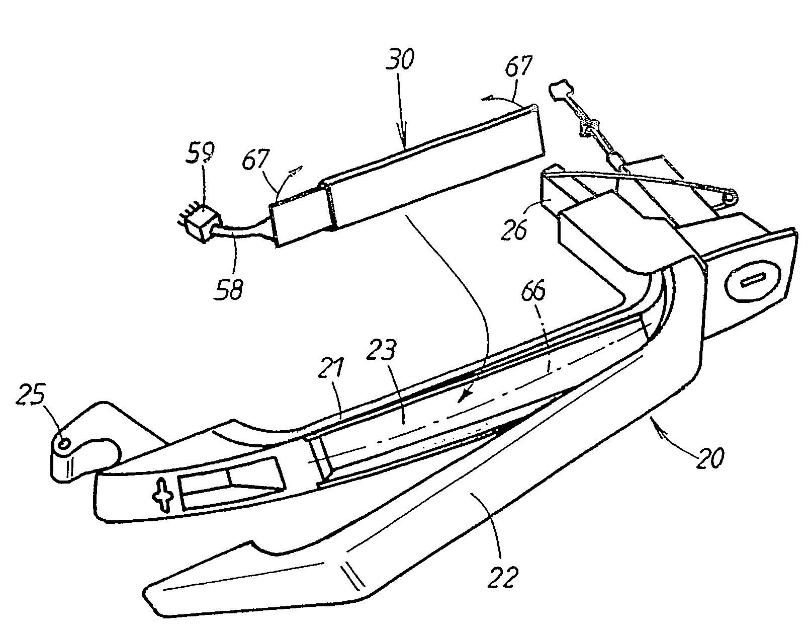
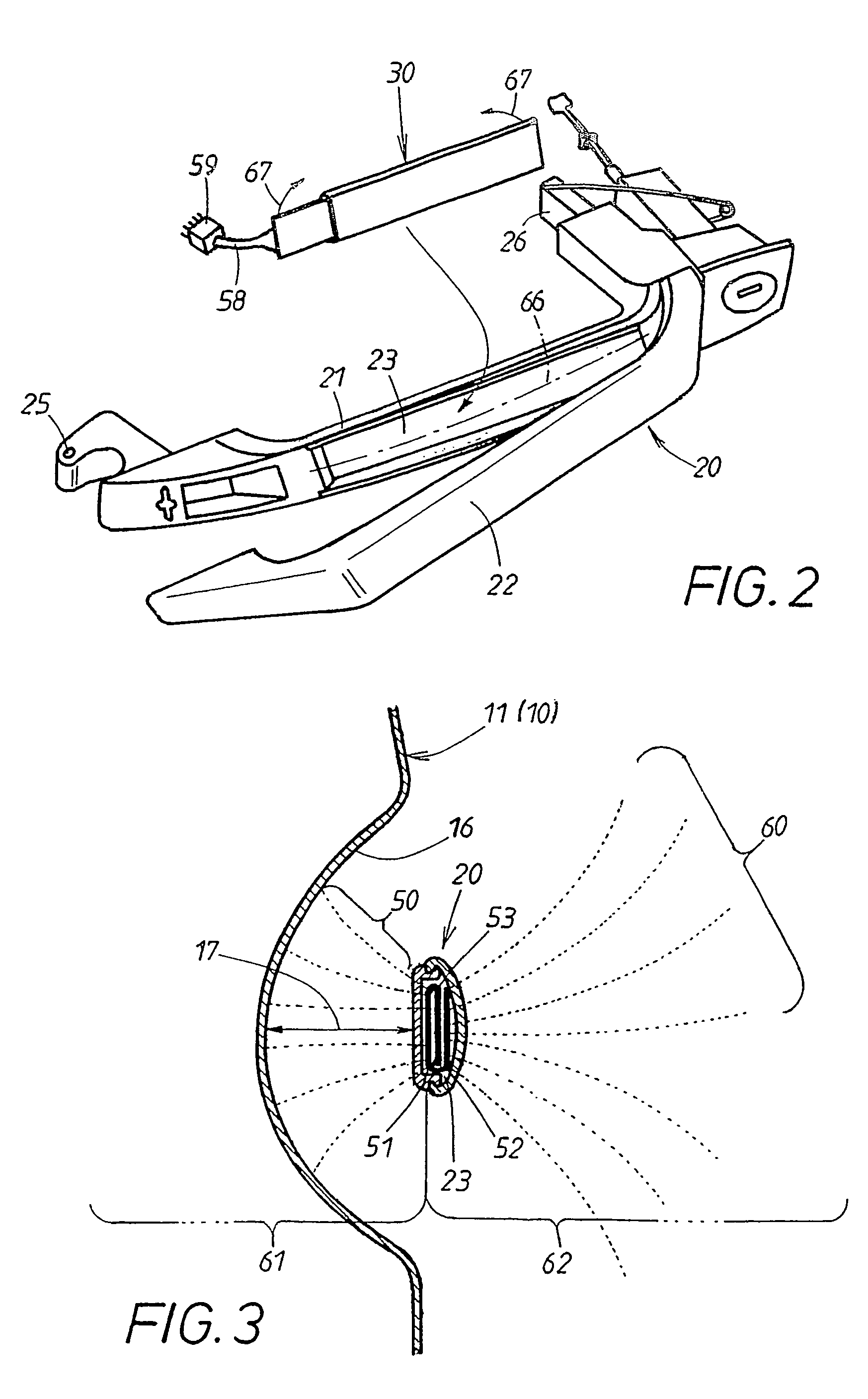
[0021]As FIG. 2 shows, the handle can have a two-part design, consisting, for example, of a base shell 21 and a cover shell 22, between which a space 23 is present to hold a separate electrical ...


PUM


Abstract

The invention relates to a closing system comprising handles (20) for operating latches that are inoperative when in a locked position, and only enable the latch to open when the latch is in an unlocked position. In conjunction with an access authorization device, the approaching of a hand to the handle (20) can be sensed in advance by a capacitive sensor thus enabling a very early reversing of the latch into the respectively desired position. To this end, two electrodes (51, 52) are integrated inside the handle (20), and a shielding (53) is located between these electrodes. One electrode (51) generates an inner field (50) between the handle (20) and the vehicle (10) and, with the vehicle body, acts as a capacitive inner sensor. The other electrode (52),however, generates an outer field (60) with regard to the surrounding area of the vehicle. When, during normal use of the handle (20), the hand passes into the area of the inner field (50), a first function in the latch or vehicle is carried out. In contrast, when the hand is brought towards the handle (20) from the outside, the dielectric properties in the outer field (60) are altered thereby leading to a second function in the latch or vehicle.

Description

BACKGROUND OF THE INVENTION[0001]1. Field of the Invention[0002]The invention pertains to a lock system which comprises an access authorization device, which consists of a stationary part in the vehicle and a mobile part carried by the authorized person. A specific function in the lock or in the vehicle is triggered upon the initiation and successful completion of a data exchange between the mobile part and the stationary part.[0003]2. Description of the Related Art[0004]It is known that a capacitative sensor in the handle can be used to initiate this data exchange (DE 196 17 038 C2). This sensor creates a uniform field in the area of the handle and responds when a human hand approaches the field. Then the previously mentioned data exchange begins; and, upon completion of this exchange, the function by which the lock is switched to its release position is triggered. This lock system offers the advantage that the lock is switched to its release position even before the handle is actu...

Claims


Application Information

Patent Timeline
Patent Type & Authority Patents(United States)
IPC IPC(8): E05B3/00E05B65/20E05B65/26
CPCE05B81/77E05B81/78Y10S292/25Y10S292/30Y10T292/57E05B7/00E05B17/22
Inventor MÜLLER, BENJAMINVAN DEN BOOM, ANDREASSCHUMACHER, HELMUT
Owner HUF HULSBECK & FURST GMBH & CO KG
Learn More