Closure cap

a technology of retaining flap and closure, which is applied in the field of closing flap, can solve the problems of reducing the maximum length of the retaining flap, tampering evidence present in the closing twist, and achieve the effects of improving the rigidity of the flap, and increasing the contact area

Inactive Publication Date: 2008-11-04
OBRIST CLOSURES SWITZERLAND GMBH
View PDF34 Cites 11 Cited by
  • Summary
  • Abstract
  • Description
  • Claims
  • Application Information

AI Technical Summary

Benefits of technology

[0009]In order that the vertical force applied to the frangible connection is maximised the flaps need to be positioned as vertically as possible, whilst maintaining contact under the retaining bead. The spacer means of the flaps push the flaps away from the container neck, reducing the angle between the flap and the main wall of the tamper-evident band.
[0010]A particularly pertinent application of the present invention is for beer bottles. Closure caps which are used for beer bottles preferably have a shorter skirt and tamper-evident band than is standard to imitate a metal crown. So-called short twist-off closures present problems with tamper-evidence because the vertical distance the closure moves is reduced. In addition, the tamper-evident band needs to be as short as possible, which consequently reduces the maximum length of retaining flaps. Reliable tamper-evidence must be achieved whilst retaining ease of application. The ability to maximise forces applied to the frangible connection allows the height of the closure to be reduced. A standard 28 mm diameter closure is approximately 19 mm tall (including the tamper-evident band). Using the present invention closures of 14.4 mm have proved to function reliably. The reduction in height gives a corresponding reduction in material.
[0011]The use of hinged flaps which are moulded in a downward condition and then folded into the closure prior to application is an advantage, because the flaps can hinge towards the tamper-evident band as they pass over container retaining bead. However, the nature of plastics materials is such that the flaps try to return to their original downward-most position, i.e. away from the tamper-evident band wall and towards the neck finish. This means that the flaps tend to move to a less vertical inclination, with a corresponding reduction in the vertical force exerted on an annular retaining bead.
[0014]The spacer means may be formed by a fold in part of the flap. For example, by folding part of a flap radially inwardly (when the flap is in use) this may be used to produce a fin. As an additional benefit, by folding the flap its rigidity can be improved. Because the flap is inclined upwards and inward after placement on to the container and the flaps engage with their free edge onto the container, the forces arising during opening of the closure cap are transferred by the flaps to the tamper-indicating band approximately along their longitudinal axis. The use of folds which may, for example, be along the longitudinal axis of the flap can be used to improve the rigidity of the flap in that direction. In this case therefore the flaps can brace more firmly against the container in addition to being pushed away from it. In one embodiment in which two lateral fins are created through an inward folding of the edges of the flap, the width of the fins increases towards the free edge of the flap to increase the area of contact with the container. Corrugated flaps could be used but this uses more material than flaps which are simply folded once at either side to form lateral fins.
[0015]In one embodiment the thickness of the flap is substantially uniform throughout its length. This is particularly relevant to flaps in which an inward folding is used to improve the retention of the flaps against the tamper-evident bead on the container.

Problems solved by technology

So-called short twist-off closures present problems with tamper-evidence because the vertical distance the closure moves is reduced.
In addition, the tamper-evident band needs to be as short as possible, which consequently reduces the maximum length of retaining flaps.

Method used


Image

  • Closure cap
  • Closure cap
  • Closure cap

Examples


Embodiment Construction

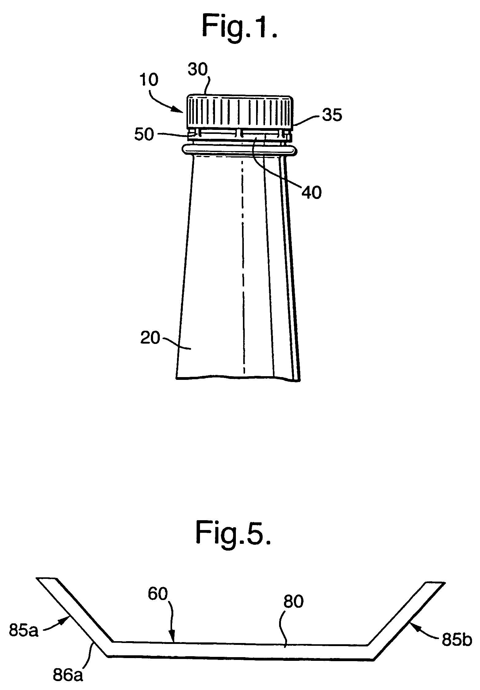
[0029]Referring first to FIG. 1 there is shown a closure cap generally indicated (10) which is attached to a container neck (20), in this case-from a beer bottle. The closure cap (10) comprises a top panel (30) with a cylindrical skirt (35) depending from its periphery. A tamper-evident band (40) is frangibly connected to the open end of the skirt (35) by a plurality of frangible bridges (50). The length of the cap (10) is approximately 14 mm; a standard plastics cap for bottles is approximately 20 mm. In this embodiment the cap (10) as a whole and the band (40) are much shorter than usual, although of course the present invention is not limited to such closures. Whilst not illustrated, the cap may include a liner, such as a gas scavenging liner, which may be particularly useful for products such as beer which are sensitive to oxygen.

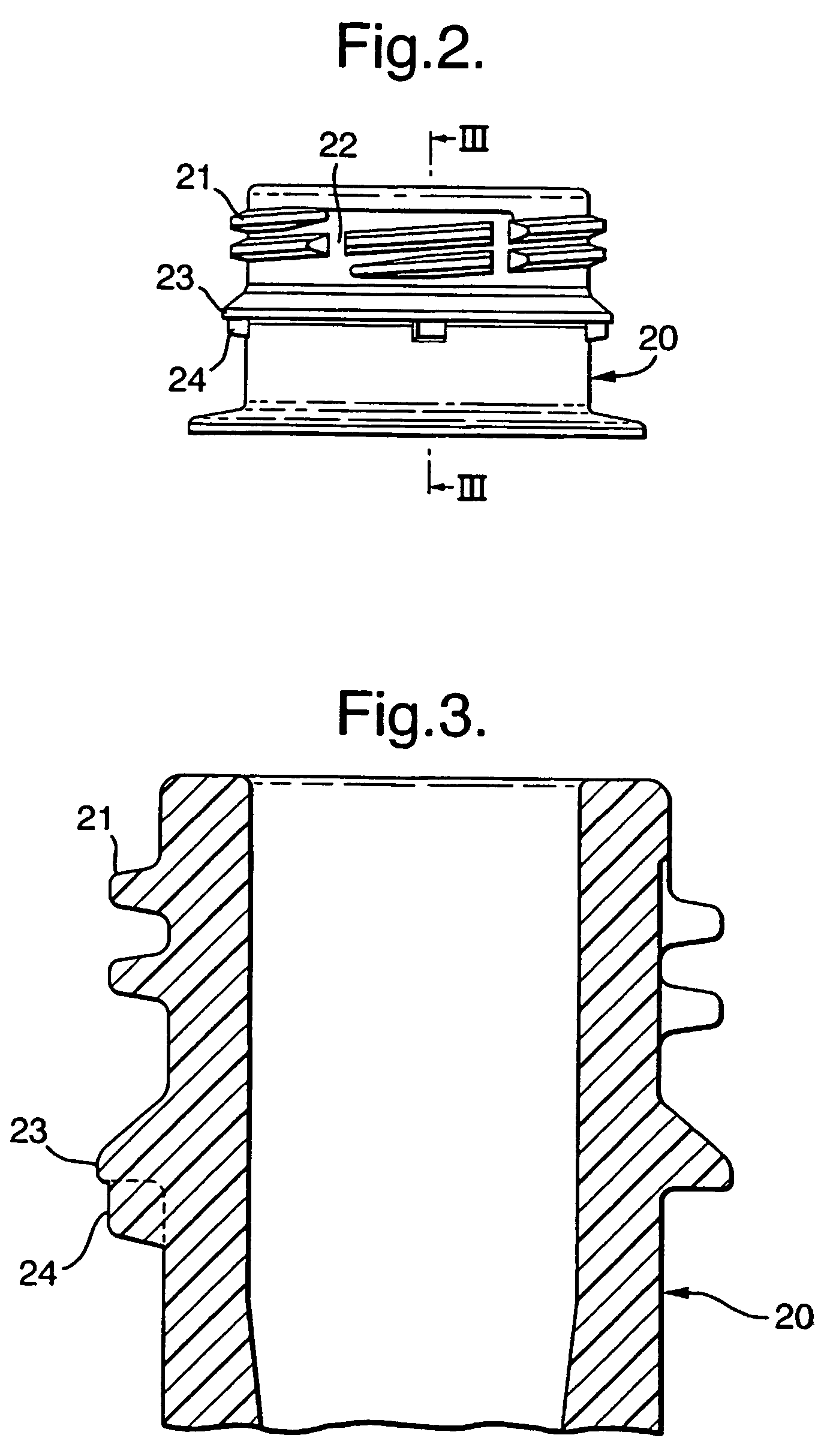
[0030]Referring now to FIGS. 2 and 3, the-container neck (20) is shown in more detail. The neck (20) has a single start thread (21) which includes seve...


PUM


Abstract

A closure (10) is provided and includes a tamper-evident band (40). The band (40) has a plurality of retaining flaps (60) which engage under a container neck annular retaining bead (23) when the closure is first applied. The flaps have a ratchet surface (86a, 190) for engaging a complimentary surface on the container neck (20). The flaps also have spacer means (85a, 85b, 186) for pushing them into a more vertical inclination under the bead (23). The ratchet arrangement and spacer means ensure reliable separation of the tamper-evident band (40).

Description

BACKGROUND OF THE INVENTION[0001]The present invention is concerned generally with a closure cap having a tamper-indicating band, and particularly to such a closure in which a plurality of flaps are provided on the tamper-indicating band for engaging an annular retaining bead on a container to retain the band on the container.[0002]Closure caps of this type generally comprise a top panel with a cylindrical skirt depending from the periphery thereof. A tamper-indicating band is in some way frangibly connected to the open end of the skirt. The tamper-indicating band has retaining flaps which extend radially inwardly and towards the top panel to allow engagement under an annular retaining bead on a container. When the closure cap is removed from the container for the first time, for example by unscrewing, the flaps apply torque to the band and prevent the band from following the upper portion of the cap in its upwardly translational movement. The tamper-evident band is retained on the ...

Claims


Application Information

Patent Timeline
Patent Type & Authority Patents(United States)
IPC IPC(8): B65D41/34
CPCB65D41/3428
Inventor BOSL, UDOHABERSAAT, PATRICK
Owner OBRIST CLOSURES SWITZERLAND GMBH
Why Eureka
Try Eureka