
Remote estimation of round-trip delays in a data network

a data network and distance estimation technology, applied in data switching networks, instruments, frequency-division multiplexes, etc., can solve problems such as network congestion and access to all network diagnostic tools, and achieve the effect of diagnosing network congestion

Active Publication Date: 2008-10-28
CITRIX SYST INC
View PDF5 Cites 47 Cited by
  • Summary
  • Abstract
  • Description
  • Claims
  • Application Information

AI Technical Summary

Benefits of technology

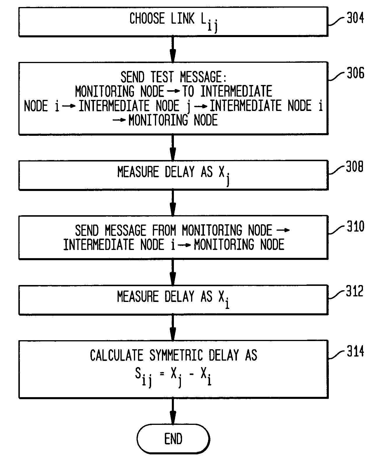
The present invention provides an improved technique for diagnosing network congestion. The invention involves measuring the time delay between transmission and receipt of test messages between network nodes to determine the path delay between two network nodes. This path delay can be used to identify possible suspect path segments that are causing the congestion. The test procedure can be repeated with each iteration reducing the set of possible suspect path segments by approximately one-half. The invention also allows for the determination of queuing delays by subtracting traffic independent delays from the measured delay times of the test messages. These technical effects can help to improve network congestion diagnosis and facilitate network management.

Problems solved by technology

Perceived network congestion may be due to various network elements, some of which may be the responsibility of the ISP under the SLA, and others of which are not the responsibility of the ISP and not guaranteed by the SLA.
Either way, the party monitoring the service is not the network service provider, and therefore does not have access to all of the network diagnostic tools at the disposal of the network provider.
As such, it is generally difficult for a third party observer to accurately pinpoint the portion of a data network causing delays.

Method used


Image

  • Remote estimation of round-trip delays in a data network
  • Remote estimation of round-trip delays in a data network
  • Remote estimation of round-trip delays in a data network

Examples


Embodiment Construction

[0021]FIG. 1 shows a packet data network 100 in which the principles of the present invention may be implemented. Network 100 contains multiple network nodes which are connected by network links. Networks, such as network 100, are well known in the art of data networking. Nodes (generally shown in FIG. 1 as “N”) in such networks are generally network routers which receive data packets and forward the data packets on toward their final destination via another router. Routers are generally implemented using standard network interfaces and their operation is controlled by one or more processors executing computer program instructions. The implementation of data networks, including network routers, is well known in the art and will not be described in detail herein.

[0022]Consider source node 104 (which may be, for example, a server of an e-commerce company) and destination node 102 (which may be, for example, a point of presence (POP) used to connect user computers to the data network)....


PUM


Abstract

Disclosed is a technique for data network congestion diagnosis using remote estimation of round-trip delays. A monitoring node transmits test messages between network nodes and measures the transit times between when the test messages are transmitted from, and when they return to, the monitoring node. A path delay between network nodes is determined based on the measured time delays. The techniques for determining network path delay are also utilized in conjunction with a three phase test procedure for diagnosing network congestion problems. Due to various network topologies and routing tables, certain confirmatory checks may be required to determine whether the procedures of the first or second phase test procedures are appropriate for particular path segments. Further, queuing delays may be determined by subtracting traffic independent delays from the measured transit times of the test messages, and such queuing delays may be used to determine the path delays. Such traffic independent delays may be determined during periods of low network traffic.

Description

BACKGROUND OF THE INVENTION[0001]The present invention relates generally to data networks, and more particularly to estimating round trip path segment delay in a data network.[0002]Quality of Service (QoS) is becoming increasingly important to e-commerce companies doing business over the Internet (or other data networks). Such companies offer various services to their customers over the Internet, including the ability to perform commercial transactions. These companies generally maintain one or more web servers which provide the online functionality to their customers. The connectivity of these web servers to the Internet is provided by Internet service providers (ISP). Since much of the success of an e-commerce company depends upon the quality of the connection of their web servers to the Internet, such companies are interested in negotiating service level agreements (SLA) with their ISPs. An SLA defines the level of service which the ISP will provide to the company and may guarant...

Claims


Application Information

Patent Timeline
Patent Type & Authority Patents(United States)
IPC IPC(8): H04J1/16
CPCH04L43/0864H04L45/00H04L43/0852
Inventor NEIDHARDT, ARNOLD L.CHANDRAMOULI, YEGNANARAYANAN
Owner CITRIX SYST INC
Learn More