Process and apparatus for the hydrogenation of chlorosilanes
a chlorosilane and hydrogenation technology, applied in mechanical equipment, machines/engines, silicon compounds, etc., can solve the problems of increased corrosion of components and high thermal stress on components, and achieve the effect of simple operation
- Summary
- Abstract
- Description
- Claims
- Application Information
AI Technical Summary
Benefits of technology
Problems solved by technology
Method used
Image
Examples
example 1
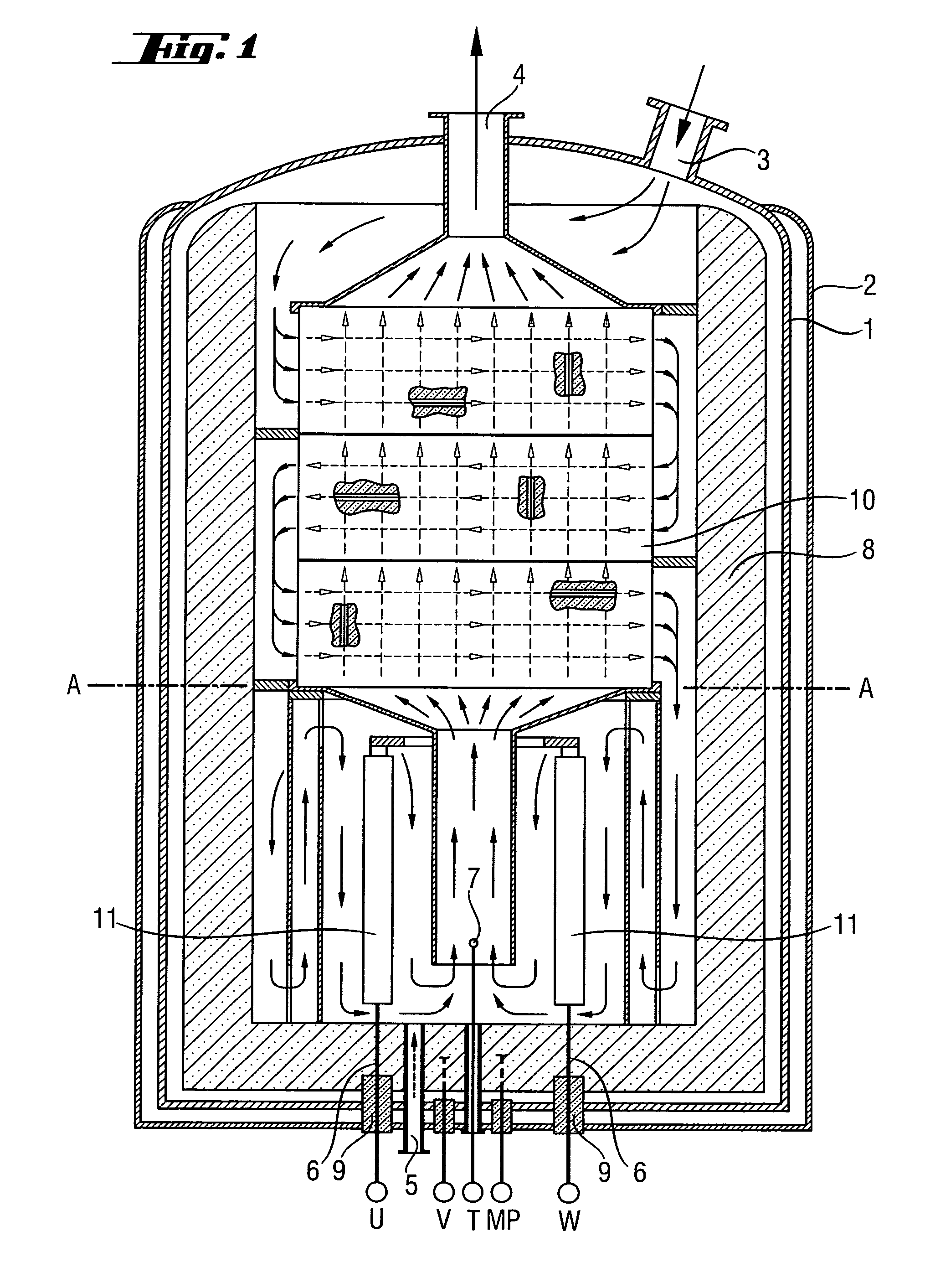
[0043]Coating using a chlorosilane / H2 mixture was carried out as first process step in a reactor as shown in FIG. 1. The progress of the coating process was monitored by means of the change of the resistance of the heating elements. The reactor was firstly brought to the target temperature (1300° C.) at a hydrogen throughput of 150 m3 / h at only a slightly superatmospheric pressure (1.5 bar). The chlorosilane was then fed in. Over a period of 48 hours, the throughput of hydrogen was increased to 1500 m3 / h and that of chlorosilane was increased to 5 metric t / h. Over this time, the pressure was increased to 6 bar. Silicon tetrachloride and purified hydrogen from the synthesis of TCS were used as starting materials.
[0044]The coating process was stopped after about 72 hours. Test specimens were taken and examined in terms of their chemical resistance as described in Example 3.
[0045]The thickness of the SiC layer on the structural elements was 10-100 μm (depending on the temperature at th...
example 2
[0046]A reactor which had been coated as described in Example 1 and, for comparative purposes, a reactor with uncoated graphite components as was used in Example 1 were used under the following conditions for the hydrogenation of SiCl4: Reactor temperature 900° C., pressure 5 bar, molar ratio of H2:SiCl4=2:1, SiCl4 throughput 8 metric t / h.
[0047]The reactor with the uncoated components had to be shut down after a period of operation of less than 6 months. The reactor with the coated components was shut down after 12 months. The two reactors were compared after the end of the period of operation. The uncoated components displayed considerable corrosion and had to be discarded. The coated components showed barely any corrosion and could be reused for the next period of operation. The operating life of the coated reactor components had more than doubled compared to the components of the comparative reactor; the specific energy consumption per amount of TCS produced had been reduced by a...
example 3
[0048]The test specimens which had been coated in situ in the reactor (see Example 1) were compared with other test specimens. For this purpose, test specimens made of various materials were introduced into a reactor as shown in FIG. 1 in order to examine their chemical resistance under the conditions of the hydrogenation of SiCl4 (1000° C., H2:SiCl4=2:1, duration of experiment 3 months).
[0049]The chemical resistance was estimated from the changes in the surface structure and the loss in mass of the test specimens. The results are summarized in Table 1.
[0050]
TABLE 1Test specimensWeight changeSurfaceGraphite parts coated in+2.1%unchangedsitu from Example 1SiC-precoated graphite+0.9%unchangedpartsGraphite+24% (due to SiSiC depositionuptake)Graphite / graphite−40% (part Si uptake,SiC depositionfiberspart decomposition)Ceramic based−100%Completelyon SiO2decomposedCeramic based−100%Completelyon Al2O3decomposed
No difference was found between the chemical resistance of the test specimens pre...
PUM
| Property | Measurement | Unit |
|---|---|---|
| temperature | aaaaa | aaaaa |
| temperature | aaaaa | aaaaa |
| pressure | aaaaa | aaaaa |
Abstract
Description
Claims
Application Information
 - R&D
- Intellectual Property
- Life Sciences
- Materials
- Tech Scout
- Unparalleled Data Quality
- Higher Quality Content
- 60% Fewer Hallucinations
Browse by: Latest US Patents, China's latest patents, Technical Efficacy Thesaurus, Application Domain, Technology Topic, Popular Technical Reports.
© 2025 PatSnap. All rights reserved.Legal|Privacy policy|Modern Slavery Act Transparency Statement|Sitemap|About US| Contact US: help@patsnap.com

