
Optimal heat engine

a heat engine and optimal technology, applied in the direction of connecting rods, bearings, shafts and bearings, etc., can solve the problems of inability to reduce cannot be conservative, and cannot have any effect on the efficiency of the system, so as to increase the efficiency of the heat engine

Inactive Publication Date: 2008-10-28
FSNC
View PDF9 Cites 8 Cited by
  • Summary
  • Abstract
  • Description
  • Claims
  • Application Information

AI Technical Summary

Benefits of technology

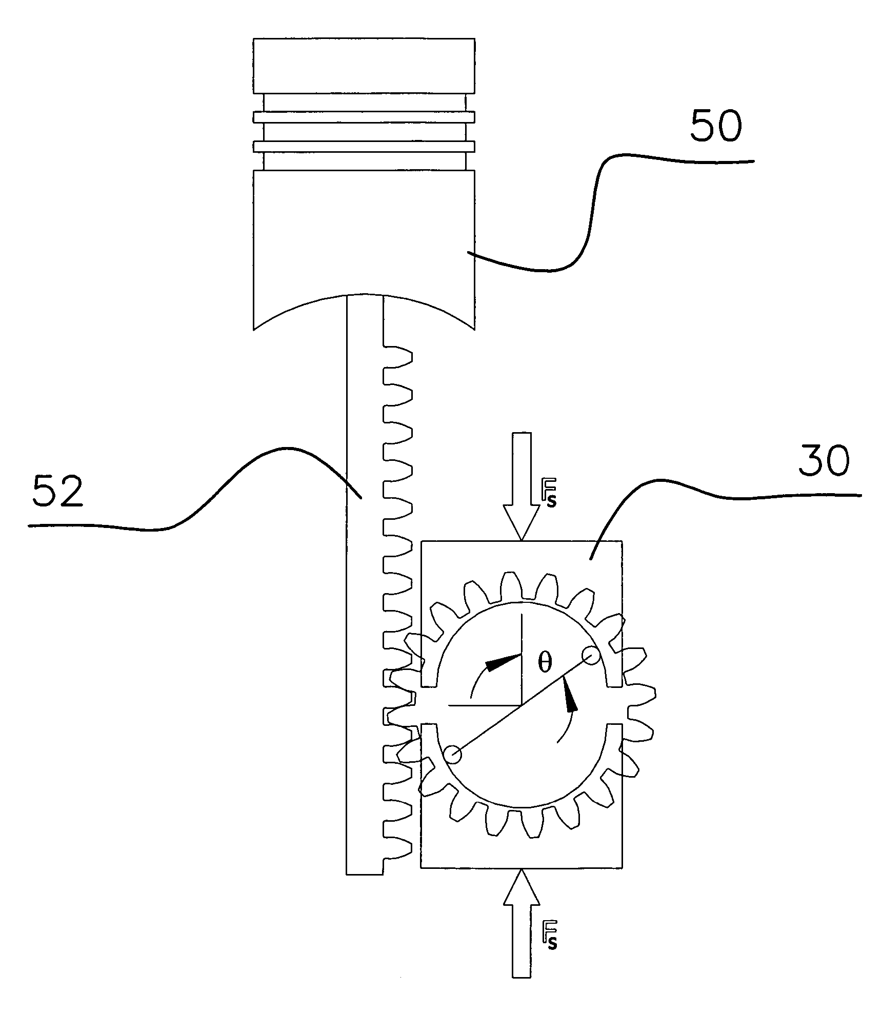
[0040]In light of the state of the art and the discovery described above, it is the object of this invention to increase the efficiency of heat engines by minimizing the work performed by the engine in compressing the working substance. This is achieved by coupling the engine to a conservative force mechanism that cyclically stores and returns potential energy to the engine. In particular, the invention exploits the physical relationship expressed in Equation 20 to develop a generic mechanism capable of performing the work required to drive the reciprocating component of the engine against compression so that the inefficient thermodynamic process does not have to.

Problems solved by technology

Therefore, a force resulting from a spinning flywheel cannot be the gradient of a potential energy function and, subsequently, cannot be a conservative force.
Therefore, it has been considered not to have any effect on the efficiency of the system.
Unfortunately, increasing the compression ratio is not without difficulty in an internal combustion engine because fuel tends to spontaneously ignite at relatively low values of compression.
Alternatively, Diesel-cycle engines maximize the compression ratio by injecting fuel after maximum compression is reached, which in turn produces spontaneous combustion of the fuel.
Such efforts at maximizing compression ratios to optimize the efficiency of internal combustion engines were essentially exhausted by the time of the oil crisis in the 1970s.
Therefore, engineers turned to the next most well-known impediment to engine efficiency; that is, the incomplete burning of the fuel introduced into the engine.

Method used


Image

  • Optimal heat engine
  • Optimal heat engine
  • Optimal heat engine

Examples


Embodiment Construction

[0070]The heart of the invention lies in the realization that the presence of an adjunct conservative force in a reciprocating machine can be used advantageously to reduce the energy required of an inefficient source to drive it. In a conventional reciprocating heat engine, in which conservative forces arise from the displacement of a piston or other equivalently moveable member (such as the rotor of a rotary engine) due to change in volume of the working medium of the engine, this reduction is achieved by coupling a supplemental force to the piston over a range of its motion in such a manner as to counterbalance those forces. Without loss of generality, the counterforce may be viewed as a force that pushes the piston into the cylinder with the identical force as a function of position as the force with which the gas repels the piston out of the cylinder.

[0071]There are two conceptually general categories of coupling techniques that may be employed to effectively counter these press...


PUM


Abstract

A conservative force coupled to the piston of a reciprocating-piston engine, refrigerator, or compressor acts to counter the pressure force on the piston that arises from the change of volume of the working substance accompanying a change in the piston position. As a result, the efficiency of the engine, refrigerator, or compressor is improved to approach the theoretical thermodynamic limit of the underlying process.

Description

RELATED APPLICATIONS[0001]This application is based on U.S. Provisional Application Ser. No. 60 / 635,593, filed Dec. 13, 2004.BACKGROUND OF THE INVENTION[0002]1. Field of the Invention[0003]The invention relates, in general, to reciprocating machines for converting thermal energy into mechanical force or, conversely, using mechanical work to transfer thermal energy from one region to another. In particular, the invention relates to mechanisms designed to produce position-dependent conservative forces to counter the conservative forces that arise from the change in volume of the machine's working medium.[0004]2. Description of the Prior Art[0005]Conservative forces are defined as those forces that are a direct result of a potential energy field and, therefore, are a function only of position. As a consequence, it is sufficient and necessary that they derive from the gradient of a potential energy function. The work a conservative force does on an object in moving it from point A to B ...

Claims


Application Information

Patent Timeline
Patent Type & Authority Patents(United States)
IPC IPC(8): F02B75/32
CPCF02B75/32
Inventor TINKER, FRANK A.
Owner FSNC
Learn More