
Optometric apparatus

a technology of optometry and reference position, which is applied in the field of optometry equipment, can solve the problems of large difference between the examination power and the resultant power through conversion of the reference position of the spectacle wearing the spectacle wearing the reference position, and the inability to perform high-precision examinations. achieve the effect of high precision

Inactive Publication Date: 2008-10-21
NIDEK CO LTD
View PDF17 Cites 4 Cited by
  • Summary
  • Abstract
  • Description
  • Claims
  • Application Information

AI Technical Summary

Benefits of technology

[0006]The present invention has been made in view of the above circumstances and an object to overcome the a

Problems solved by technology

However, even though a difference between lens power and power through conversion for the spectacles wearing reference position is arranged to fall within the respective permissible difference in respect to each of the plurality of the lenses (single lens), when they are combined, the difference between the examination power and the resultant power through conversion for the spectacles wearing reference position becomes large.
Under such circumstances, an examination of high precision may not be performed.

Method used


Image

  • Optometric apparatus
  • Optometric apparatus
  • Optometric apparatus

Examples


Embodiment Construction

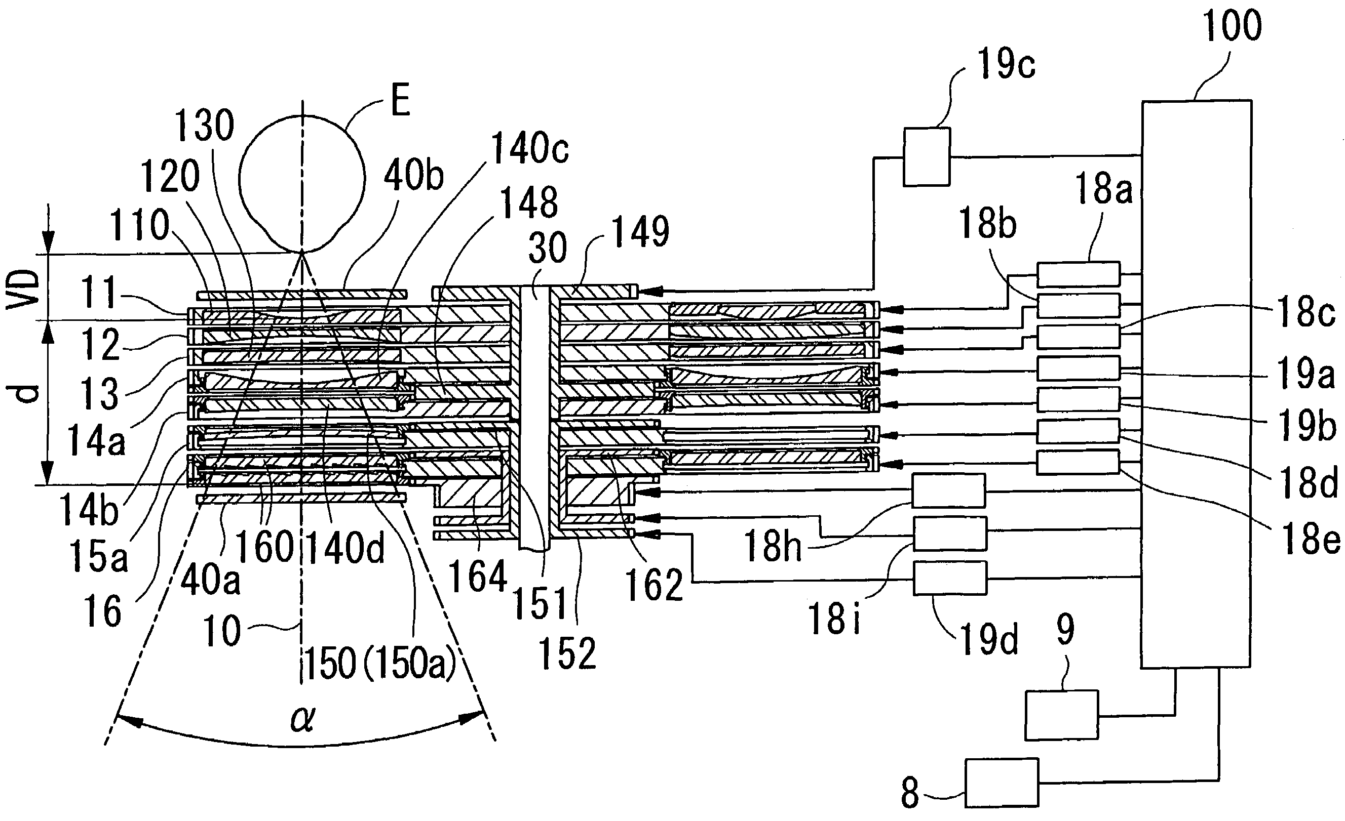
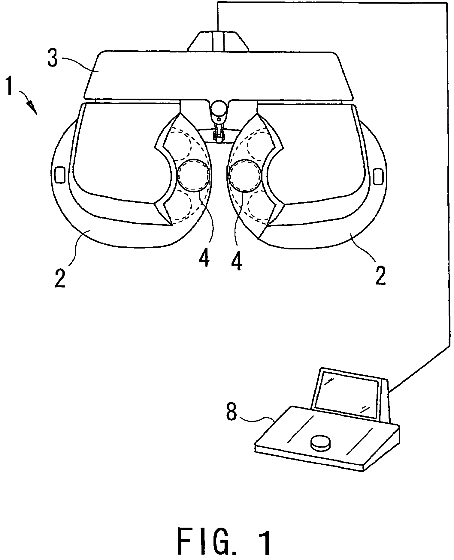
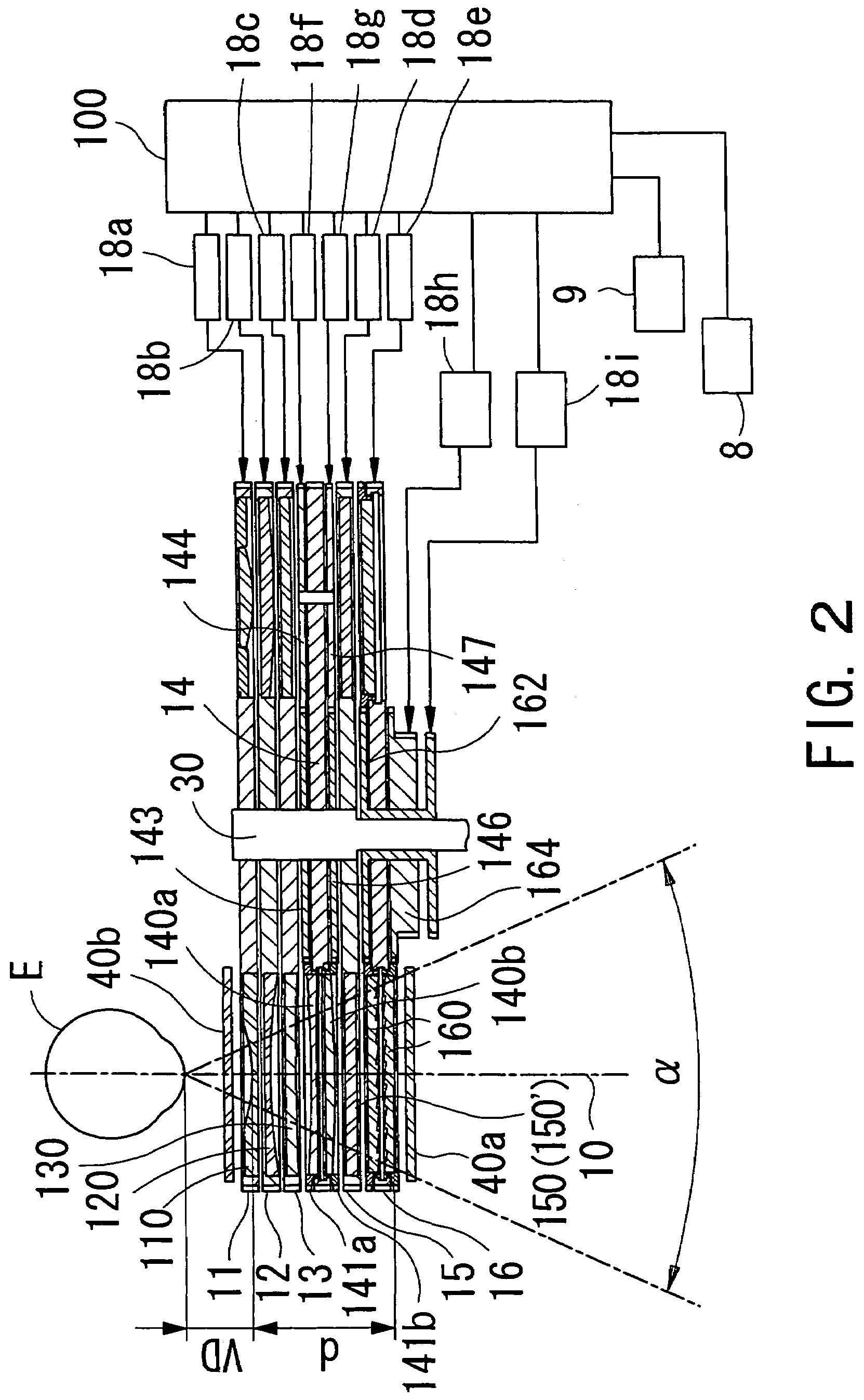
[0020]A detailed description of one preferred embodiment of an optometric apparatus consistent with the present invention will now given referring to the accompanying drawings. FIG. 1 is a front view showing an appearance of a subjective optometric apparatus consistent with the preferred embodiments when viewed from the examiner's side. A main body 1 of the optometric apparatus includes a pair of symmetric lens chamber units 2 and a moving unit 3 which suspends and supports (holds) these right and left lens chamber units 2 and has a sliding mechanism for adjusting an interval between the both units 2, and a convergence mechanism for adjusting a convergence angle (an intorsion angle) between the both units 2. The right and left lens chamber units 2 are provided with a test window 4 where after-mentioned optical elements such as a lens are to be arranged. A controller 8 inputs an operation signal into the main body 1.

[0021]FIG. 2 is a view describing the optical elements arranged in t...


PUM


Abstract

An optometric apparatus for examining refractive power of an examinee's eye subjectively, capable of performing highly-precise examination. The apparatus has a test window through which a presented optotype is seen, a first spherical-power applying unit which applies spherical power to the eye by changing a combination of spherical lenses in the window, a cylindrical-power applying unit which applies cylindrical power to the eye by changing a relative angle of a cylindrical axis of cylindrical lenses in the window, a second spherical-power applying unit including a spherical lens for correction, an instruction unit which instructs examination spherical and cylindrical power, a power-determining unit which determines power applied by the power-applying units so that a difference between the instructed examination power, and resultant spherical and cylindrical power through conversion for a spectacles wearing reference position falls within a predetermined permissible difference, and a control unit which controls driving of the power-applying units.

Description

BACKGROUND OF THE INVENTION[0001]1. Field of the Invention[0002]The present invention relates to an optometric apparatus for examining (measuring) refractive power of an eye of an examinee subjectively.[0003]2. Description of Related Art[0004]There is known an optometric apparatus in which optical elements such as a spherical lens and a cylindrical lens are arranged in a test window provided in front of an eye of an examinee, and a forward-presented optotype is shown via the arranged optical elements for subjectively examining (measuring) the eye. And such apparatus is proposed that a plurality of spherical lenses with different power are arranged in three disks for spherical lenses, and the disks are rotated respectively to change a combination of the spherical lenses which are to be arranged in the test window so that spherical power (spherical refractive power) is applied to the eye. Also, proposed is an apparatus such that a plurality of cylindrical lenses with different power a...

Claims


Application Information

Patent Timeline
IPC IPC(8): A61B3/02A61B3/028A61B3/04
CPCA61B3/0285A61B3/04D04B15/60D04B15/322
Inventor HAYASHI, AKIHIROHOSOI, YOSHINOBUHOSHINO, HIDETAKA
Owner NIDEK CO LTD
Learn More