Pneumatic tire with specified bead portion profile

a pneumatic tire and profile technology, applied in the field of pneumatic tires, can solve the problems of increasing the constant of the vertical spring, insufficient cornering power, and insufficient steering stability, so as to enhance steering stability, enhance the rim binding force, and improve the riding comfort. the effect of comfor

Inactive Publication Date: 2008-10-21
SUMITOMO RUBBER IND LTD
View PDF7 Cites 1 Cited by
  • Summary
  • Abstract
  • Description
  • Claims
  • Application Information

AI Technical Summary

Benefits of technology

[0007]It is an object of the present invention to provide a pneumatic tire in which a rim binding force in a heavy load state is increased as compared with that in a normal running state to complement insufficiency of cornering power in the heavy load state, thereby enhancing the steering stability under a severe running condition such as high speed cornering without deteriorating the riding comfort.
[0013]According to the pneumatic tire of the present invention, in a load state, it is possible to bring the flange receiving surface portion of the bead portion into contact with the flange surface at a high contact position under high contact pressure. Therefore, it is possible to largely increase the rim binding force in the heavy load state as compared with that in the normal running state. As a result, it is possible to complement the insufficiency of the cornering power in the heavy load state, and to enhance the steering stability under a severe running condition such as high speed cornering without deteriorating the riding comfort.

Problems solved by technology

Thus, in the heavy load state, the cornering power becomes insufficient, and the steering stability can not be exhibited sufficiently.
An example of means for enhancing the cornering power is to enhance the rigidity of the bead portion itself by increasing the amount of bead apex rubber b shown in FIG. 5 and by providing a cord reinforcing layer c. However, this means has a problem that the vertical spring constant is increased and the riding comfort is deteriorated.

Method used


Image

  • Pneumatic tire with specified bead portion profile
  • Pneumatic tire with specified bead portion profile
  • Pneumatic tire with specified bead portion profile

Examples


examples

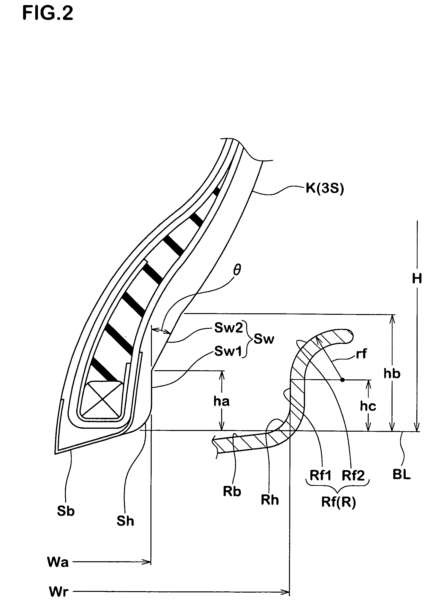
[0042]Tires for passenger vehicle having the structure shown in FIG. 1 and tire size of 215 / 40R17 were prototyped based on the specification shown in Table 1. The steering stability and riding comfort of the prototyped tires were measured and compared with each other. The specifications other than those shown in Table 1 are the same. The rims used here were standard rims (17×7.5JJ) of JATMA standard, the height hc of the vertical surface portion Rf1 in the flange surface Rf is 9.0 mm, the radius of curvature of the curved surface portion Rf2 is 9.0 mm.

[0043](1) Steering Stability and Riding Comfort;

[0044]The prototyped tires were mounted to four wheels of a vehicle (2000 cc, FR vehicle) having rims (17×7.5JJ) with internal pressure of 230 kPa, and the vehicle was allowed to run on an ordinary road and a circuit course having dry asphalt road surface. The steering stability (cornering performance on the ordinary road, cornering performance on the circuit course, lane-changing feeling...


PUM


Abstract

A bead portion 4 of a pneumatic tire 1 includes a vertical rising surface portion Sw1 which is connected to a bead base surface Sb through an arc bead heel surface Sh, and a straight or convex arc flange receiving surface portion Sw2 which is diagonally extending from the rising surface portion Sw1 radially outward and axially outward of the tire. In a normal internal pressure in which no load is applied, the flange receiving surface portion Sw2 is not in contact with a flange surface Rf, and in a load state in which 50% or more of normal load is applied, the flange receiving surface portion Sw2 comes into contact with the flange surface Rf.

Description

BACKGROUND OF THE INVENTION[0001]1. Field of the Invention[0002]The present invention relates to a pneumatic tire in which steering stability in a heavy load state applied such as at the time of high speed cornering is improved without deteriorating riding comfort.[0003]2. Prior Art[0004]In a conventional pneumatic tire, as schematically shown in FIG. 5, a profile shape of a bead portion a is formed to match a profile shape of an inner surface of a rim R. More specifically, an outer wall surface Sw of the bead portion a supported by a flange surface Rf of the rim R comprises a vertical rising surface portion s1 rising from a bead heel surface Sh, and a concave arc surface s2 extending from an outer end of the rising surface portion s1 in a form of concave arc. A radial height ja of the rising surface portions 1 from a bead baseline BL is substantially equal to a height jf of a vertical surface portion Rf1 in the flange surface Rf, and a radius of curvature ra of the concave arc surf...

Claims


Application Information

Patent Timeline
Patent Type & Authority Patents(United States)
IPC IPC(8): B60C3/00B60C15/00B60C15/02B60C15/024
CPCB60C15/024Y10T152/10819
Inventor YOSHINAKA, NOBUYOSHI
Owner SUMITOMO RUBBER IND LTD
Why Eureka
Try Eureka