Eureka AIR delivers breakthrough ideas for toughest innovation challenges, trusted by R&D personnel around the world.

Apparatus and methods for reducing tool-induced shift during overlay metrology

a technology of overlay metrology and tools, applied in the field of micro-semiconductor metrology and inspection, can solve the problems of adversely affecting measurement precision, significant reduction in image contrast, and inability to readily ascertain the effect of overlay

Active Publication Date: 2008-10-07
KLA TENCOR TECH CORP
View PDF9 Cites 23 Cited by
  • Summary
  • Abstract
  • Description
  • Claims
  • Application Information

AI Technical Summary

Benefits of technology

[0014]In another aspect, the invention pertains to a system operable to determine overlay or misalignment error on a target. The system includes one or more processors and one or more memory configured to perform one or more of the above method operations. In a specific implementation, the system is an optical metrology tool, and in another implementation the system is a scanning electron microscope. In a further aspect, the system further includes an imaging system arranged to generate an optical beam and image of the target at each predefined position. In a specific implementation, the imaging s

Problems solved by technology

Since each metrology tool requires a different optimal focus position, the effect on the overlay cannot be readily ascertained and subtracted from the overlay result across various metrology tools.
Additionally, a small adjustment of the focus position can cause a significant reduction in the image contrast and adversely affect the measurement precision.

Method used


Image

  • Apparatus and methods for reducing tool-induced shift during overlay metrology
  • Apparatus and methods for reducing tool-induced shift during overlay metrology
  • Apparatus and methods for reducing tool-induced shift during overlay metrology

Examples


Embodiment Construction

[0024]Reference will now be made in detail to a specific embodiment of the invention. An example of this embodiment is illustrated in the accompanying drawings. While the invention will be described in conjunction with this specific embodiment, it will be understood that it is not intended to limit the invention to one embodiment. On the contrary, it is intended to cover alternatives, modifications, and equivalents as may be included within the spirit and scope of the invention as defined by the appended claims. In the following description, numerous specific details are set forth in order to provide a thorough understanding of the present invention. The present invention may be practiced without some or all of these specific details. In other instances, well known process operations have not been described in detail in order not to unnecessarily obscure the present invention.

[0025]The present invention provides techniques for obtaining a minimum tool-induced shift (TIS) value for a...


PUM


Abstract

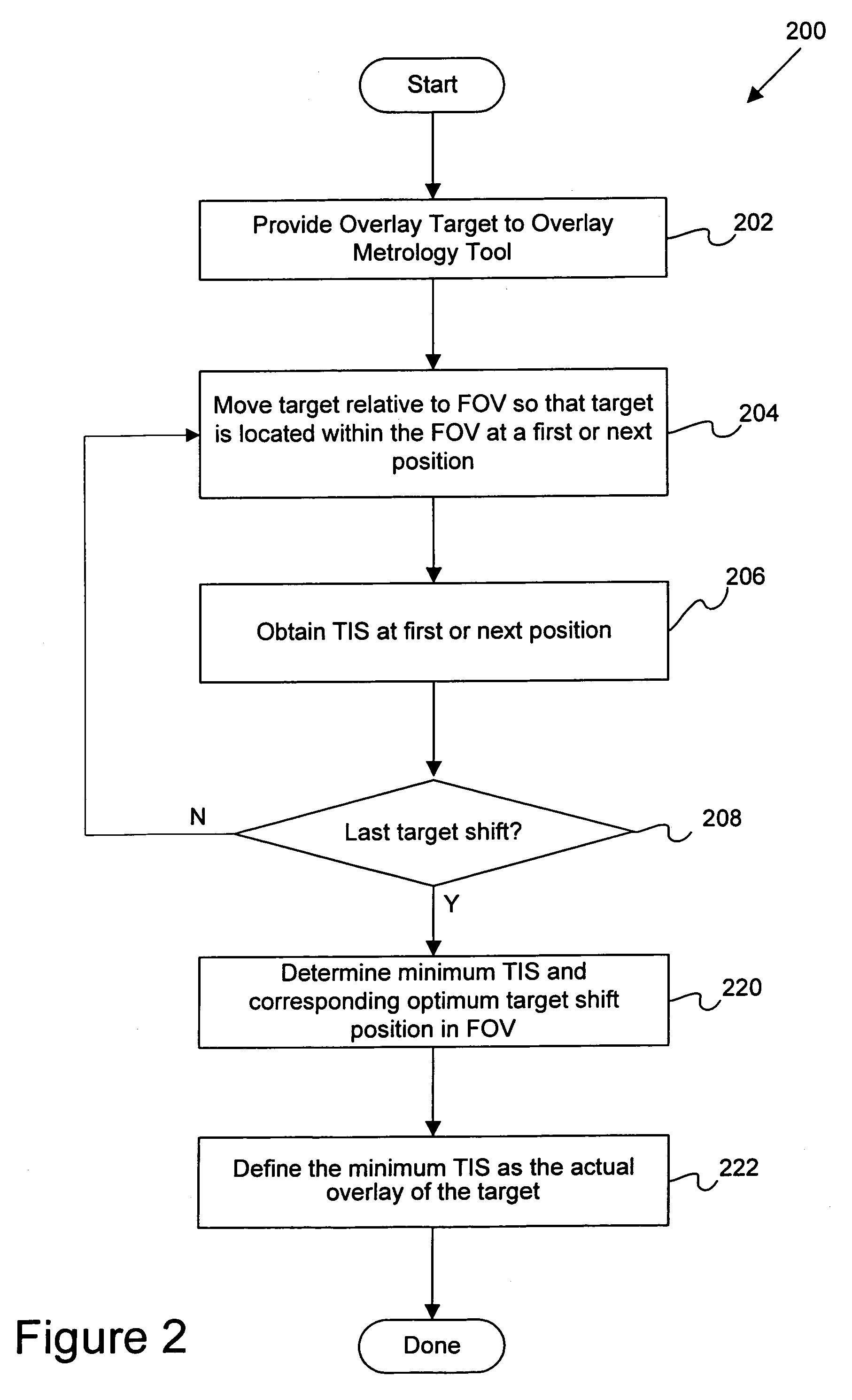
Disclosed are apparatus and methods for determining a minimum tool-induced shift (TIS) during an overlay metrology procedure. In a specific embodiment, a method of determining overlay or misalignment error on a target is disclosed. For a predefined number of positions of a target within a field of view (FOV) of a metrology tool, the following operations are performed: (i) determining a tool-induced shift (TIS) parameter value for each predefined position of the target within the FOV based on at least one overlay measurement obtained from the target at the each position (for example, based on overlay measurements at 0 and 180 degrees of wafer orientation) and (ii) determining a minimum TIS parameter value and its corresponding FOV position from the plurality of determined TIS parameters values at the predefined positions of the target within the FOV. The FOV position that corresponds to the minimum TIS is then defined as an appropriate position for the actual overlay measurement and the value of minimum TIS is used for overlay correction.

Description

CROSS REFERENCE TO RELATED PATENT APPLICATION[0001]This application claims priority of U.S. Provisional Patent Application Number 60 / 582,175, entitled APPARATUS AND METHODS FOR REDUCING TOOL-INDUCED SHIFT DURING OVERLAY METROLOGY, filed Jun. 22, 2004 by Vladimir Levinski, et al., which application is incorporated herein by reference in its entirety for all purposes.BACKGROUND OF THE INVENTION[0002]The present invention relates generally to the field of semiconductor metrology and inspection. More specifically, it relates to techniques for minimizing tool-induced shift during overlay metrology.[0003]Lithography tools used in the manufacture of integrated circuits have been around for some time. Such tools have proven extremely effective in the precise manufacturing and formation of very small details in the product. In most lithography tools, a circuit image is written on a substrate by transferring a pattern via a light beam. For example, the lithography tool may include a light sou...

Claims


Application Information

Patent Timeline
IPC IPC(8): G01B11/00
CPCG03F7/70616G03F7/70633
Inventor LEVINSKI, VLADIMIRSELA, ILAN
Owner KLA TENCOR TECH CORP
Why Eureka
Eureka Blog
Learn More