
Pressure-containing tubular connections for remote operation

a technology remote operation, which is applied in the direction of hose connections, screw threaded joints, couplings, etc., can solve the problems of difficult to obtain predictability, impair joint reliability, and still be substantial, and achieves fast, reliable and accurate pretensioning of threaded tubular connections, and reduces the amount of make up torque

Inactive Publication Date: 2008-10-07
RUSSELL LARRY R
View PDF11 Cites 24 Cited by
  • Summary
  • Abstract
  • Description
  • Claims
  • Application Information

AI Technical Summary

Benefits of technology

[0012]The invention contemplates a simple, inexpensive device for solving the problems and disadvantages of the prior approaches discussed above. The present invention provides a rapid, reliable and accurate pretensioning of threaded tubular connections in remote locations. The invention is a method and apparatus for making a pressure-containing threaded tubular connection suitable for remotely operated connection and separation. The connector of the present invention utilizes electrical heating to reduce the amount of make up torque required to produce reliable preloading of the connection and a means for biasing against the nut hub to simplify relative axial positioning of the two sides of the connector.
[0023]A further aspect of the present invention comprises: (1) a first hub having a first through bore, a cylindrical counterbore, a first conical mating surface for receiving a seal, a first interior end, and a first external surface, wherein the first hub has a plurality of threads on a portion of the first external surface; (2) a second hub having a second through bore, a second interior end, a conical seal on said second interior end sealingly comatable with the first conical mating surface, a cylindrical stabbing nose extending coaxially from said second interior end, a second outer surface, and a second hub shoulder opposed to the second interior end; (3) a coupling nut having an internally threaded proximal end adapted to threadedly engage the externally threaded first external surface, and an internal nut shoulder distal to the threaded proximal end engaged with the shoulder of the second hub to provide axial and radial position control for said coupling nut, wherein tightening the coupling nut forces the first end of the first hub towards the interior end of the second hub; (4) a heating element attached to the coupling nut; and (4) a torquing means for transmitting torque to the coupling nut to tighten or loosen the nut; whereby when the first and second hubs are brought together in a state of misalignment, interaction of the stabbing nose with the counterbore of the first hub produces coaxial alignment of the first and second hubs and when the heating element increases the temperature of the coupling nut sufficiently the coupling nut is expanded and less torque is needed to achieve a predetermined pretensioning of the tubular connector.

Problems solved by technology

However, even though the torques required to make up or break out the fasteners are less than those for a single thread pair joint, they can still be substantial.
Furthermore, unpredictable variations in friction make obtaining uniform bolting preloads unlikely, thereby impairing joint reliability.
The basic problem with all existing types of connections when used to transmit high axial and bending loadings or to seal high pressures is the need to accurately control the make up torque and friction of the threads so that a predictable value of joint preload can be obtained.
Unfortunately, such predictability is very hard to obtain, and the predictability becomes much less when the connections are remotely made in a difficult environment, such as subsea.
When the connection must be repeatedly made up and broken out remotely, joint torque predictability and, hence, connection and seal reliability become very problematic.
For such situations, thread galling, seal damage, misalignment, and the need for very high torques further complicate the problem.

Method used


Image

  • Pressure-containing tubular connections for remote operation
  • Pressure-containing tubular connections for remote operation
  • Pressure-containing tubular connections for remote operation

Examples


example 1

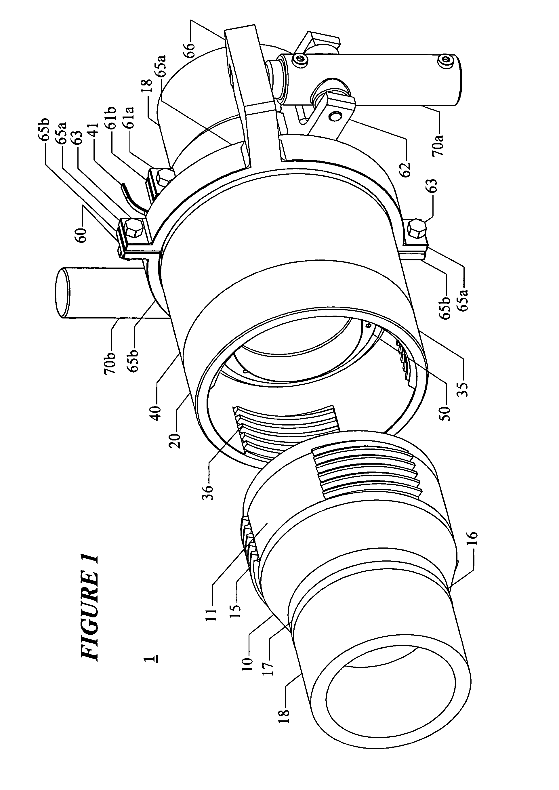
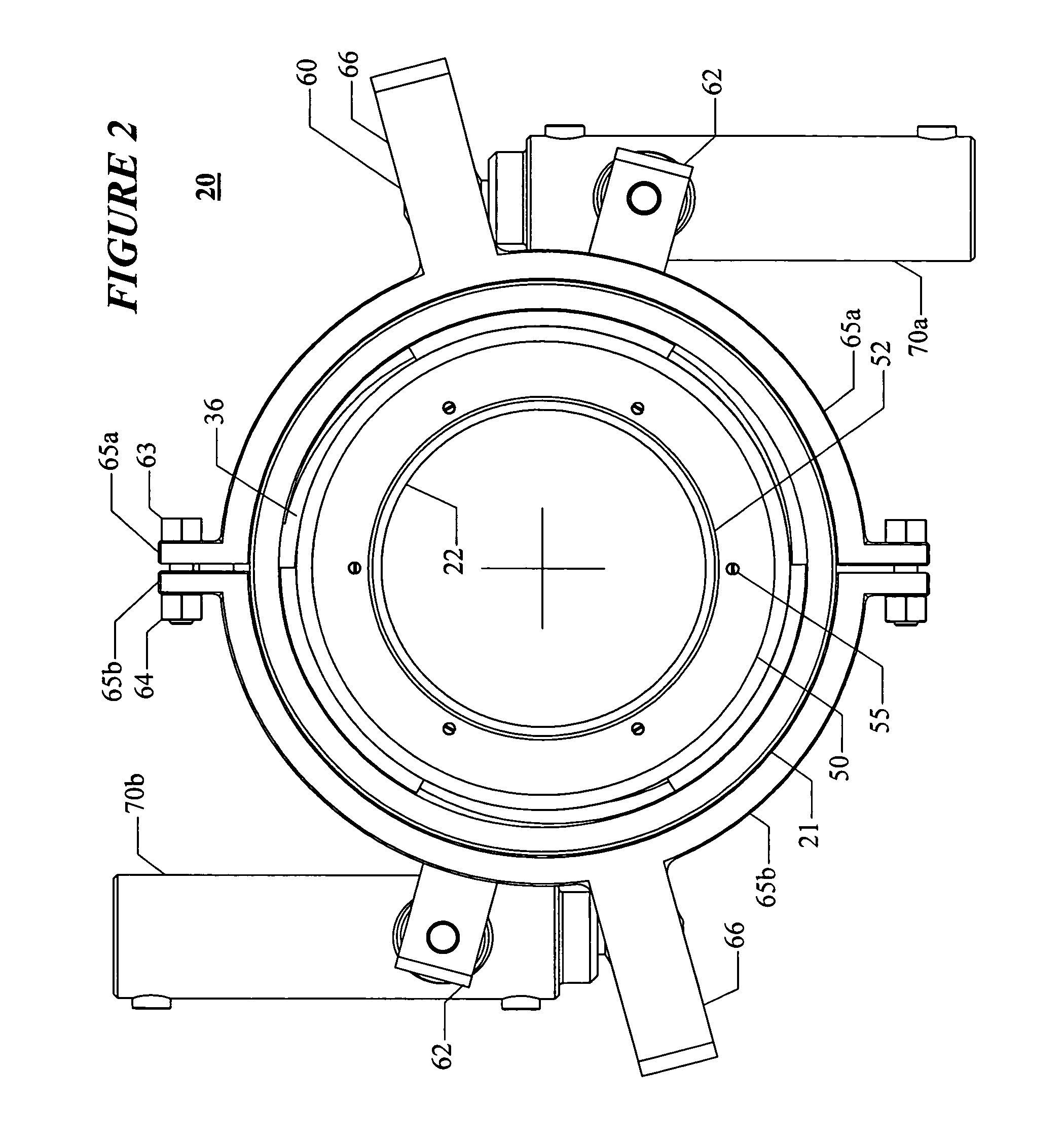
[0055]The first embodiment of the tubular connector 1 of the present invention is shown in FIGS. 1-6 and FIG. 13A. This embodiment is suitable for applications where the connection axial angular alignment and position for the connection halves are somewhat controlled, as would be the case for vertical make up in a drilling rig.

[0056]As seen in FIG. 1, the tubular connector 1 consists of two hubs, a male side 10 and a female side 20. A length of tubing 18 is connected to the male side 10 and a similar piece of tubing 18 is connected to the female side 20. The tubing 18 is connected to the male and female sides by connection means known to those skilled in the art, preferably by welding. When the two hubs are connected, flow proceeds from the tube connected to the male side 10 through the tube connected to the female side 20. Basically the tubular connector 1 connects the two pieces of tubing, by stabbing the upset male pin 11 into the nut 35 and comating the internal female threads 3...

example 2

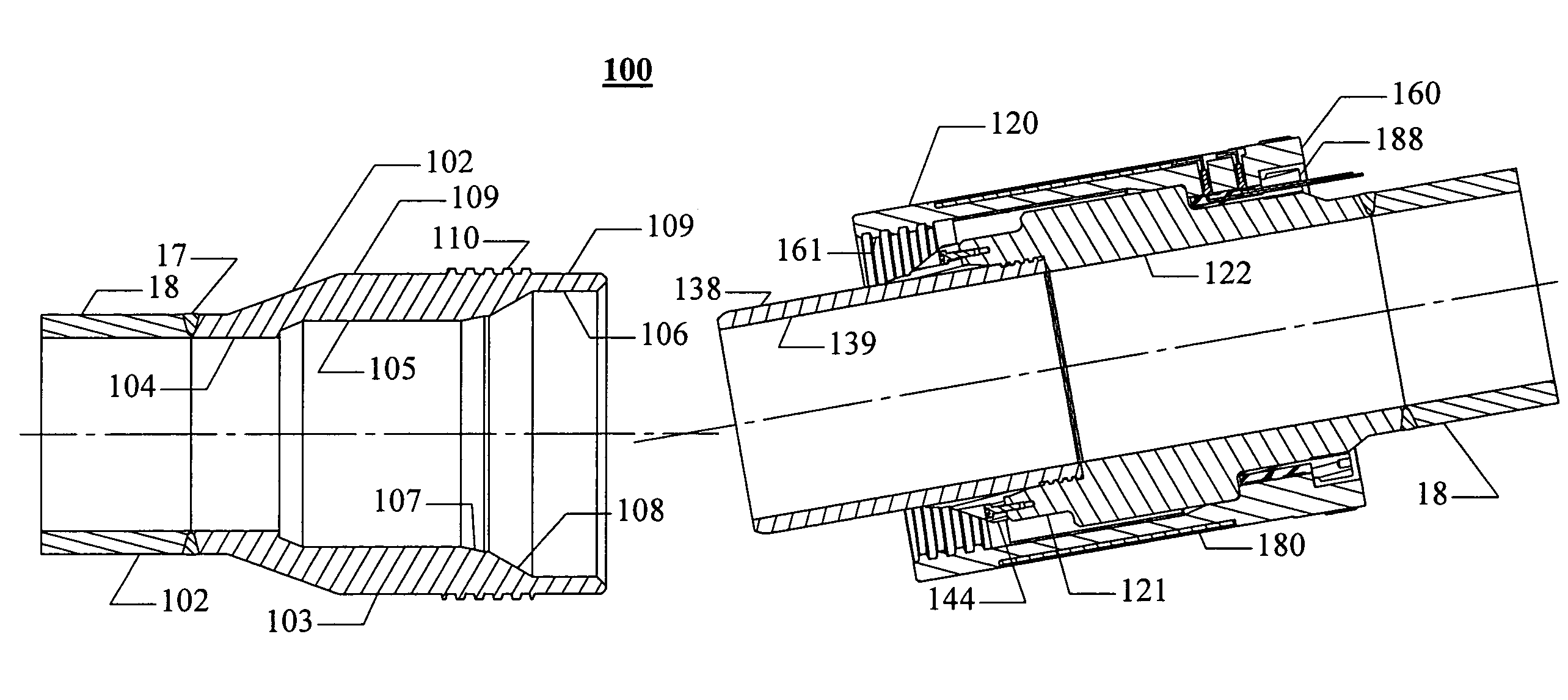
[0070]The second embodiment of the pressure containing tubular connection of this invention and its components are shown in FIGS. 7-14. This embodiment is particularly suited for situations when the connection axial angular alignment and relative position are poorly controlled during stabbing. A typical application for this connection would be a remotely made subsea pipeline pull-in connection.

[0071]As seen in FIG. 7, the tubular connector consists of a male side 102 and a female side 120. In FIG. 10, it can be seen that the male side 102 has an externally upset male pin 103 with a through bore 104, a first counterbore 105, and a second counterbore 106. Located between first counterbore 105 and second counterbore 106 is conical seal recess 107 and a larger diameter conical abutment 108 which has a larger flare angle than seal recess 107. On its exterior, pin 103 has cylindrical outer surface 109 on which continuous male thread 110 is positioned approximately in the middle. On the ou...

example 3

[0089]The third embodiment 200 of the pressure containing tubular connection is shown in FIGS. 15-18. This connector 200 uses several of the same components as the first embodiment, but uses a different pin and nut hub and seal type. Connector 200 utilizes a face seal which is suited for applications where the relative axial alignment and position of the two connection halves is closely controlled by guidance provided by the stabbing means. This type of connection would be suitable for shop make up or possibly a guided remote make up in a relatively clean environment. For this embodiment, an antirotation guide is used to effectively key the two sides of the connection together so that the face seal is not rotated across its mating surfaces. Where the components used for this third embodiment are identical to those used by the first embodiment, identical numbering and descriptions are used.

[0090]As seen in FIG. 15, the tubular connector consists of a male side 201 and a female side 2...


PUM


Abstract

This invention is a method and apparatus for making a pressure-containing threaded tubular connection, suitable for remotely operated connection and separation, utilizing electrical heating to reduce the amount of make up torque required to produce reliable preloading of the connection. One aspect of the present invention comprises: 1) a first hub with male threads on its exterior and having a sealing face and axial flow passage, b) a second hub having an axial flow passage and carrying an annular seal which can be mated with the sealing face of the first hub and mounting a rotatable nut having female threads on its interior and integral nut heating means. After stabbing and initial make-up of the connection, the nut is heated and thereby expanded in a controlled manner and the connection retightened. Following cooling, the structural connection is fully preloaded and the annular seal fully compressed so that it seals. Reversing the procedure permits disconnection.

Description

CROSS REFERENCE TO RELATED APPLICATIONS[0001]The present application is a continuation-in-part application of patent application Ser. No. 10 / 133,093 filed Apr. 26, 2002 now U.S. Pat. No. 6,764,110, and entitled “Remotely Pretensioned Threaded Tubular Connections” invented by Larry R. Russell.BACKGROUND OF THE INVENTION[0002]1. Field of the Invention[0003]The present invention relates in general to a method and apparatus for securing pressure-containing threaded tubular connections in remote or hazardous locations. More particularly, the invention relates to a method and apparatus for using electrical heating to remotely pretension pressure containing threaded tubular connections.[0004]2. Description of the Related Art[0005]Tubular connections for containing high pressure are widely used by industry, and a very large number of different types have been developed for specific needs. Several types based upon threaded connections are used frequently in oilfield applications. One very co...

Claims


Application Information

Patent Timeline
Patent Type & Authority Patents(United States)
IPC IPC(8): F16B4/00F16L35/00F16L15/08F16L37/00
CPCF16L15/08F16L37/002Y10S285/92
Inventor RUSSELL, LARRY R.
Owner RUSSELL LARRY R
Learn More