
Phosphor paste composition and method of manufacturing flat display device using the same

a technology of phosphor paste and composition, which is applied in the direction of discharge tube luminescnet screens, natural mineral layered products, cellulosic plastic layered products, etc., can solve the problems of reducing the reliability of flat panel displays, phosphorescent particles may be deteriorated by vacuum uv light, and phosphorescent particles may deteriorate during high-temperature heat treatment processes, so as to prevent phosphor deterioration and increase the life of flat display devices

Inactive Publication Date: 2008-09-30
SAMSUNG SDI CO LTD
View PDF9 Cites 15 Cited by
  • Summary
  • Abstract
  • Description
  • Claims
  • Application Information

AI Technical Summary

Benefits of technology

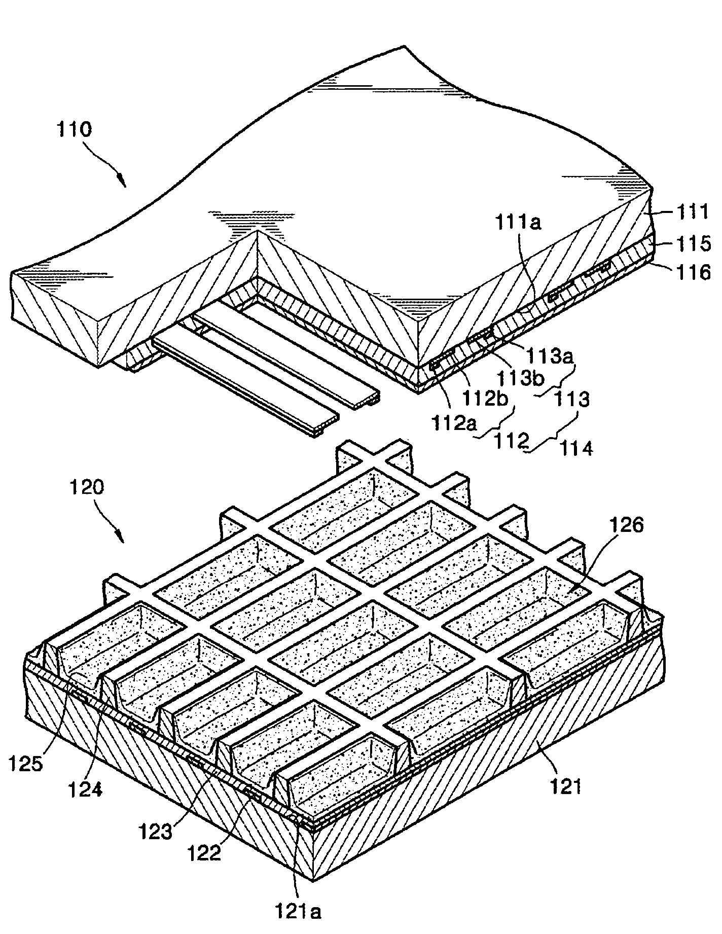
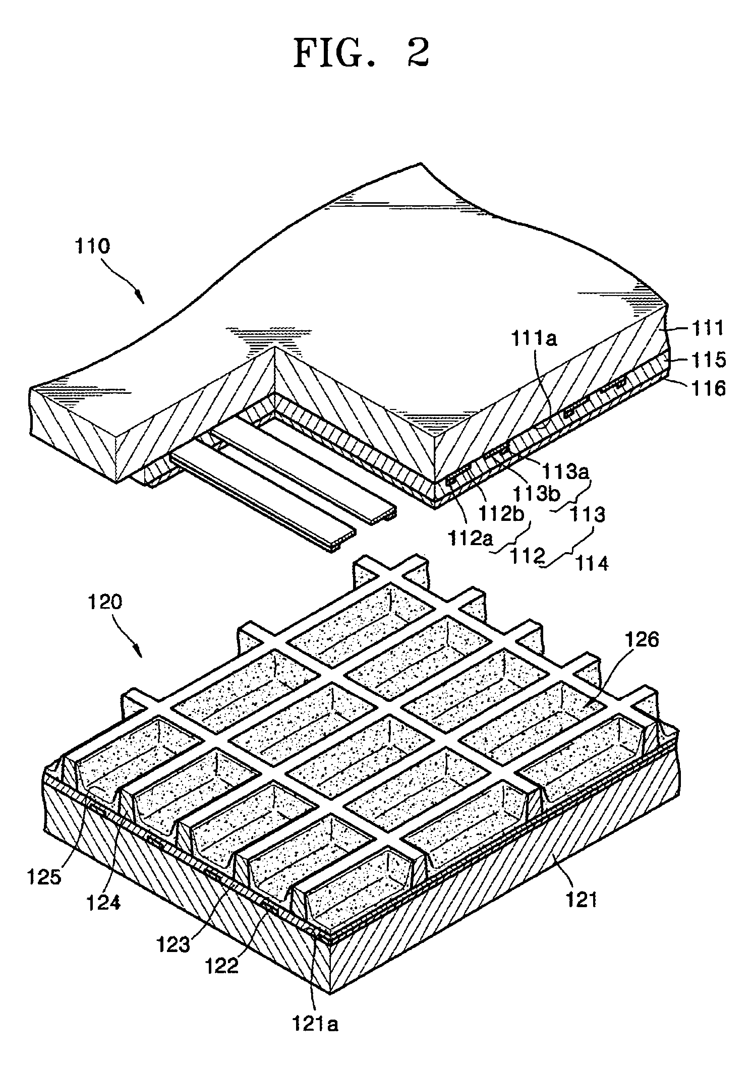
The present invention provides a phosphor paste composition that includes a phosphor coated with heat-resistant material, a binder, and an organic solvent. This composition prevents deterioration of the phosphor during heat treatment and reduces permanent residual image phenomena, resulting in a longer lifetime for the flat display device. The heat-resistant material also prevents deterioration of the phosphor due to vacuum UV light and water adsorbed by the phosphorescent particle. The method of manufacturing the flat display device involves coating the phosphor paste composition on a substrate and heat-treating it. The flat display device includes a phosphor layer made of the phosphor paste composition.

Problems solved by technology

However, when the phosphor layer is formed from the phosphor paste composition, phosphorescent particles may deteriorate during a high-temperature heat treating process.
In addition, even when a flat panel display including the phosphor layer operates, phosphorescent particles may be deteriorated by vacuum UV light, or the like.
The deterioration of the phosphor results in a decrease in the reliability of the flat panel display.

Method used


Image

  • Phosphor paste composition and method of manufacturing flat display device using the same
  • Phosphor paste composition and method of manufacturing flat display device using the same
  • Phosphor paste composition and method of manufacturing flat display device using the same

Examples


example 3

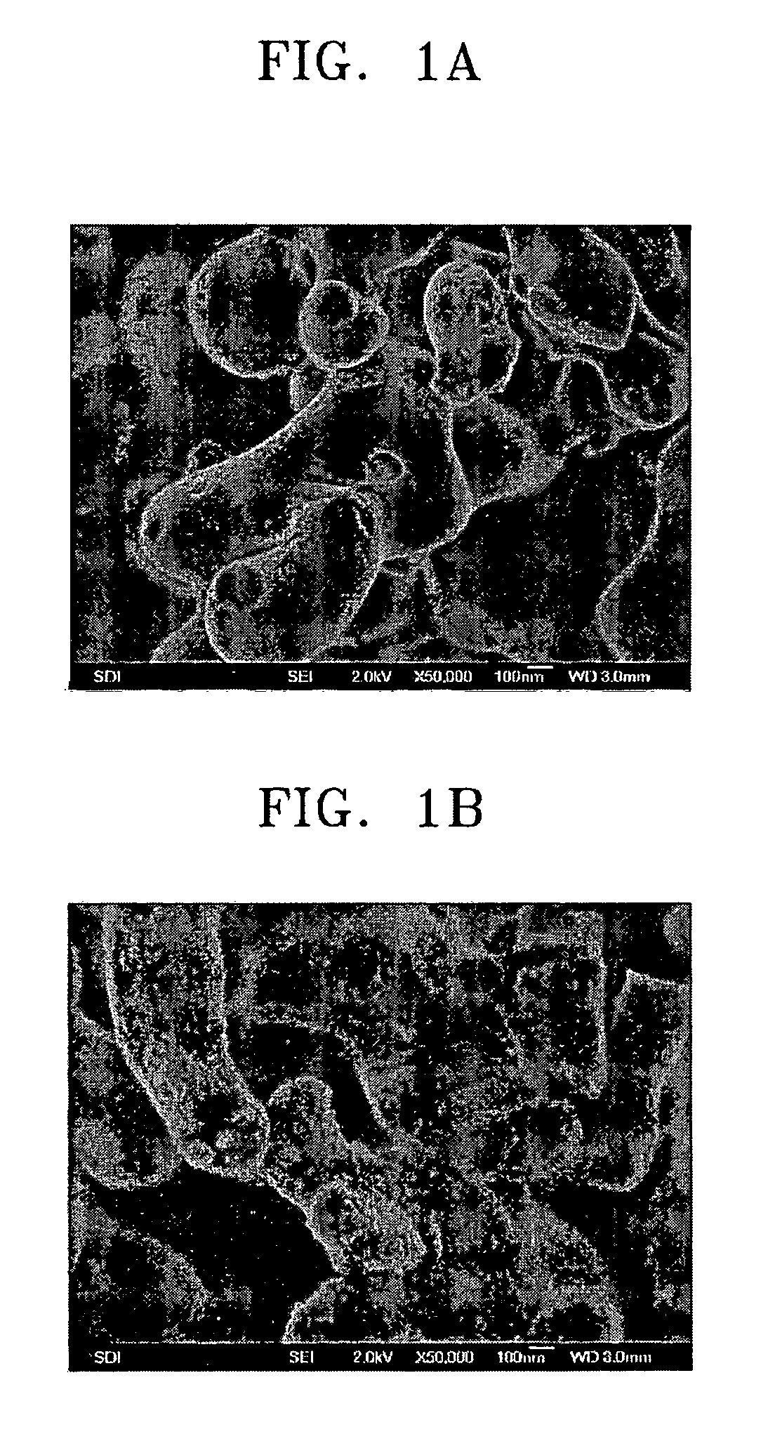
[0052]A phosphor paste composition was manufactured in the same manner as in Example 1, except that a BaMgAl10O17:Eu blue phosphor completely coated with ZrO2 was used instead of the Y(V,P)O4:Eu red phosphor completely coated with ZrO2. The phosphor paste composition manufactured according to the present example will be referred to as composition B1.

example 4

[0053]A phosphor paste composition was manufactured in the same manner as in Example 1, except that the Y(V,P)O4:Eu red phosphor was partially coated with ZrO2. The phosphor paste composition manufactured according to the present example will be referred to as composition R2.

example 5

[0054]A phosphor paste composition was manufactured in the same manner as in Example 1, except that a Zn2SiO4:Mn green phosphor partially coated with ZrO2 was used instead of the Y(V,P)O4:Eu red phosphor completely coated with ZrO2. The phosphor paste composition manufactured according to the present example will be referred to as composition G2.


PUM

PropertyMeasurementUnit
melting pointaaaaaaaaaa
diameteraaaaaaaaaa
thicknessaaaaaaaaaa

Abstract

Provided are a phosphor paste composition, a flat display device including the same, and a method of manufacturing the flat display device. The phosphor paste composition contains a phosphor with at least a heat-resistant material selected from a Group II atom-containing material, a Group III atom-containing material, and a Group IV atom-containing material, a binder, and an organic solvent. By using the phosphor paste composition, the deterioration of the phosphor can be prevented during a heat treating process. The flat display device includes a phosphor layer containing the phosphor coated with the heat-resistant material such that lifetime of the flat display device is increased and a permanent residual image phenomenon, the adsorption of water by the phosphor, and the like can be prevented.

Description

CROSS-REFERENCE TO RELATED APPLICATIONS[0001]This application claims the benefit of Korean Patent Application No. 10-2004-0081093, filed on Oct. 11, 2004, in the Korean Intellectual Property Office, the disclosure of which is incorporated herein in its entirety by reference.BACKGROUND OF THE INVENTION[0002]1. Field of the Invention[0003]The present invention relates to a phosphor paste composition, a flat display device including the same, and a method of manufacturing the flat display device, and more particularly, to a phosphor paste composition including a phosphor coated with at least a heat-resistant material selected from a Group II atom-containing material, a Group III atom-containing material, and a Group IV atom-containing material, a flat display device including the same, and a method of manufacturing the flat display device.[0004]2. Description of the Related Art[0005]Display devices mainly used in monitors of personal computers, TV receivers, or the like are important c...

Claims


Application Information

Patent Timeline
Patent Type & Authority Patents(United States)
IPC IPC(8): C09K11/00
CPCC09K11/02Y10T428/2993Y10T428/2991H01J2211/42C09K11/595C09K11/7734C09K11/7795C09K11/7715C09K11/7728C09K11/7743C09K11/7727C09K11/7712
Inventor KWON, SEUNG-UK
Owner SAMSUNG SDI CO LTD
Learn More