
Meaningful visualization of properties independent of a circuit design

Active Publication Date: 2008-09-02
JASPER DESIGN AUTOMATION
View PDF7 Cites 37 Cited by
  • Summary
  • Abstract
  • Description
  • Claims
  • Application Information

AI Technical Summary

Benefits of technology

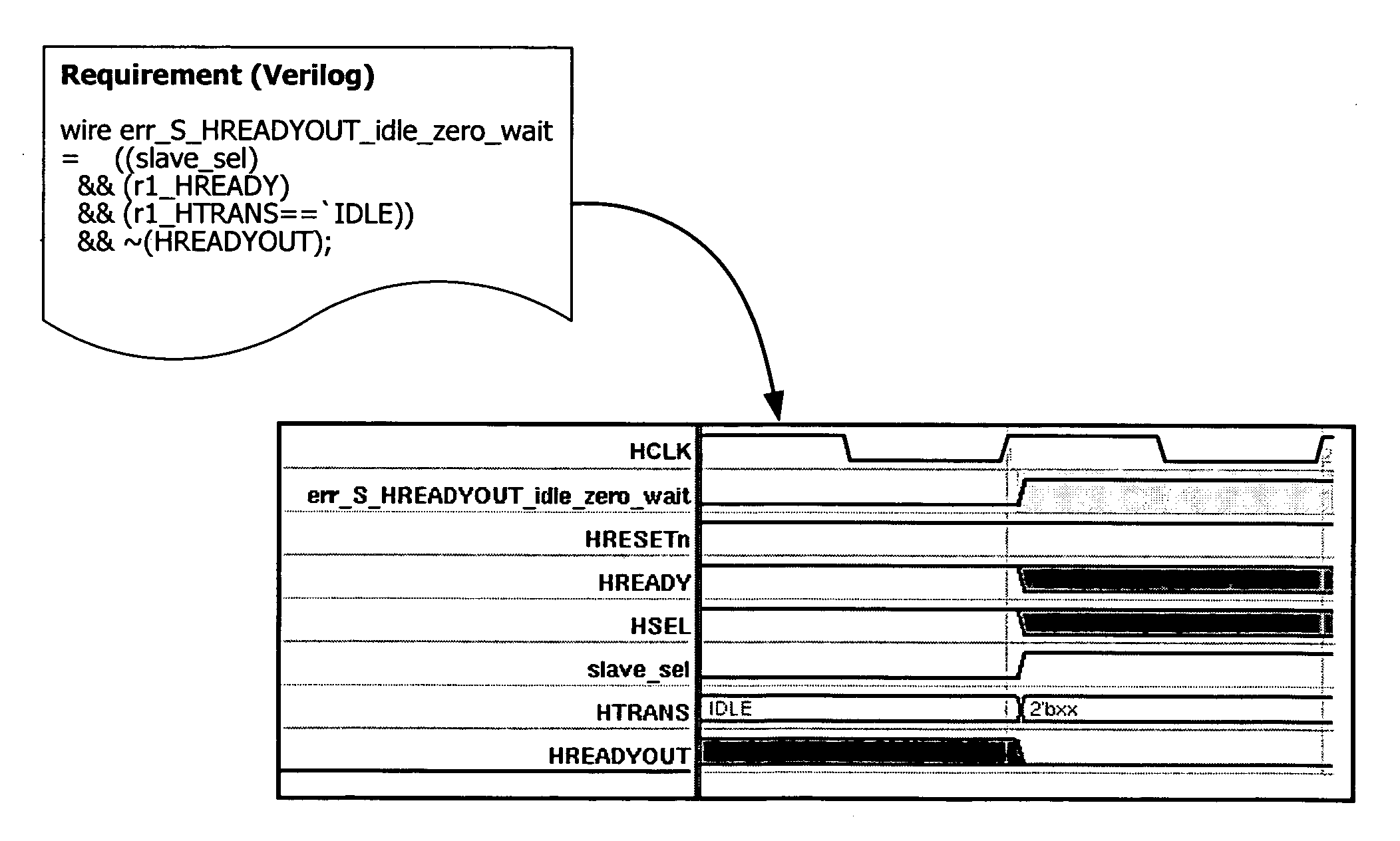
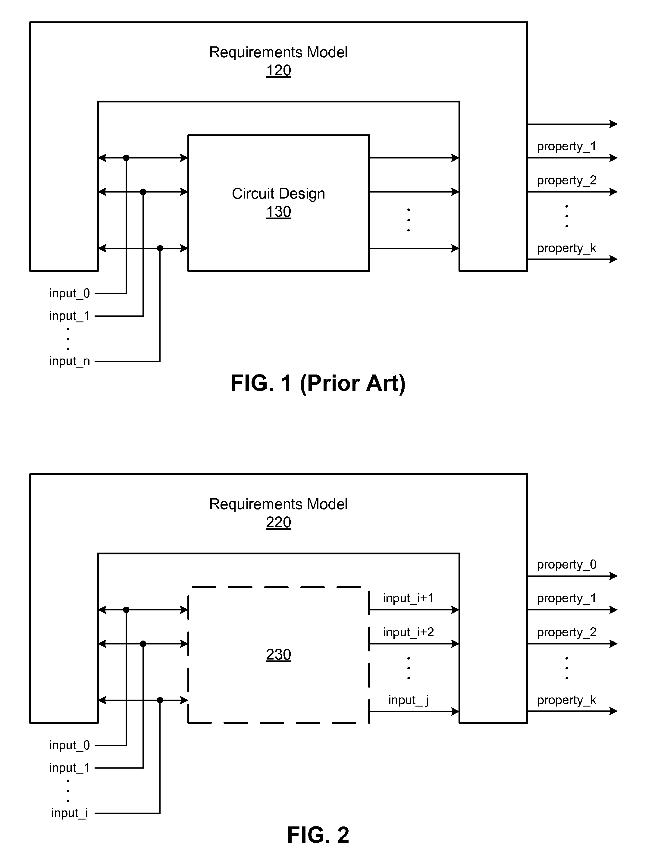
[0016]To avoid many of the problems of existing simulation and formal verification methodologies, embodiments of the invention enables a user to visualize, and therefore debug, a set of properties independently of any circuit designs for which the properties are intended. A wide range of properties can be visualized using the invention, including simple Boolean properties, simple temporal properties, and high-level properties.
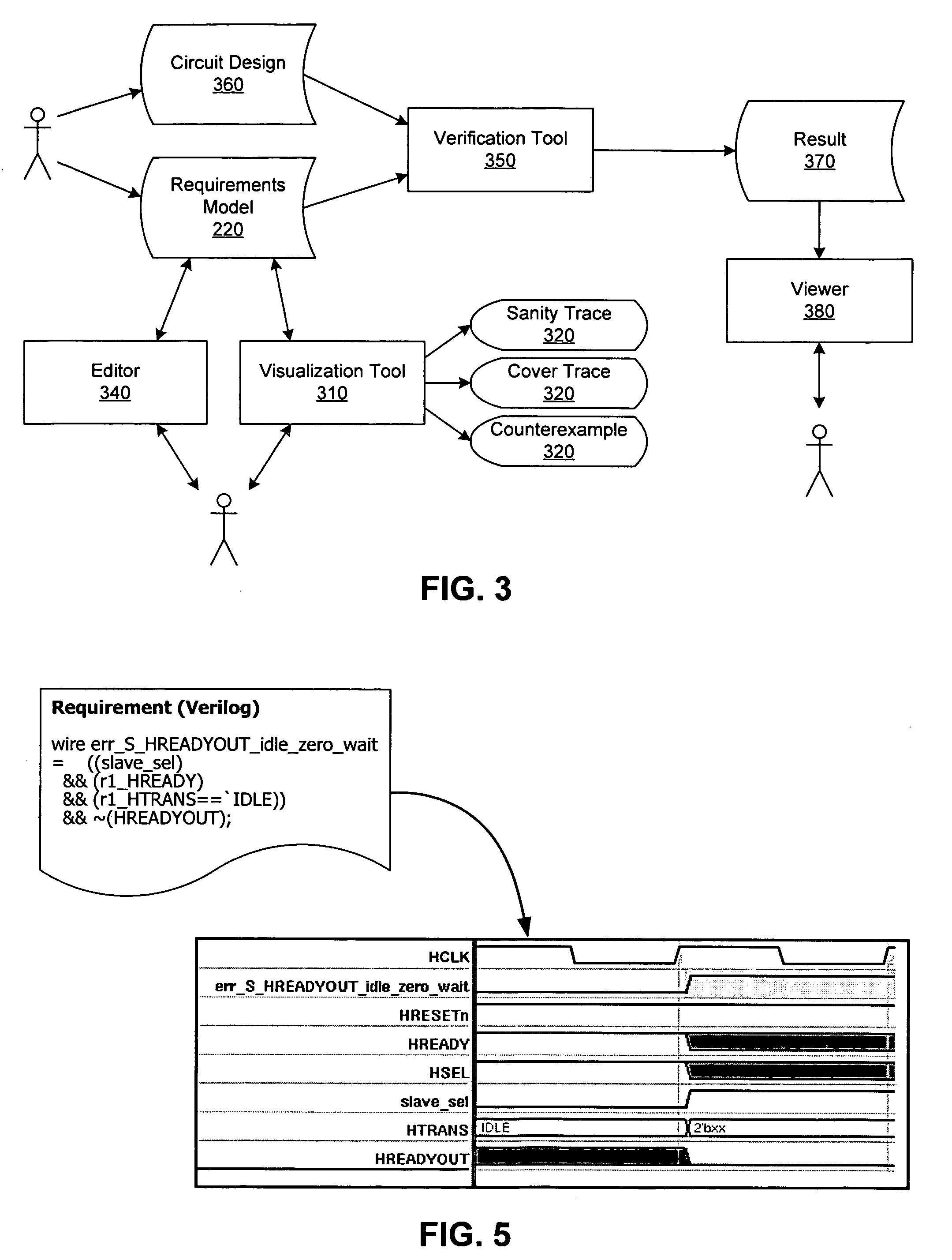
[0017]In one embodiment, visualization of a property is performed through trace generations under various temporary visualization constraints. By viewing a waveform representation or a trace of the values from a number of signals related to the specific property, a user can visualize how accurately the code reflects the actual intent of the property. One or more “meaningful” traces of the property can be obtained for visualizing different aspects of the property. A trace may show that the property is correctly modeled and illustrates the intended behavior, or it may show that the property is incorrectly modeled because it illustrates an unwanted behavior. In this way, a user can analyze the property to ascertain their correctness and appropriateness before applying them to an actual circuit design.
[0018]In another embodiment of the invention, various tools are provided for a user to visualize different traces of a property. In one example, where a property is implemented using a property signal in the requirements model (e.g., so that a violation of the property is indicated by value 0 in the property signal), a trace for the requirement illustrates the values of the property signal and a number of signals related thereto over one or more clock cycles. Embodiments of the invention include tools to allow the user to find additional traces for the property by applying various constraints to the next trace. In this way, the user can verify how a property has been encoded in the requirements model by visualizing how the property signal and its related signals act under various operating conditions. These conditions can be regarded as visualization constraints that are applied to the trace generation algorithm temporarily for the purpose of obtaining a different trace. By applying constraints to new signals cumulatively, a series of traces can be saved and navigated to allow a user to understand whether a property is modeled properly in the requirements model.

Problems solved by technology

Over the last 30 years, the complexity of integrated circuits has increased greatly.
This increase in complexity has exacerbated the difficulty of verifying circuit designs.
In a typical integrated circuit design process, which includes many steps, the verification step consumes approximately 70-80% of the total time and resources.
As a result, flaws in the design that are not found during the verification step can have significant economic impact by increasing time-to-market and reducing profit margins.
Circuit designers use high-level hardware description languages because of the size and complexity of modern integrated circuits.
Where n is large, such as for a complex design, the number of possible input sequences becomes prohibitively large for verification.
Formal verification methods are therefore more exhaustive when compared to simulation methods.
Otherwise, errors detected during the verification process may reflect errors in the properties rather than a true error in the circuit design that is being verified.
When high-level requirements and their requirement model are debugged along with the circuit design during the formal verification process, the complexity of the debugging effort is further increased.
While in some cases the requirements can be simulated with simulation vectors to determine their correctness, it is generally difficult to create simulation vectors to simulate assertions or requirements that do not represent a self-contained, high-level model of the design.
Such a concurrent verification scheme of debugging the design and the verification components at the same time leads to inefficiencies in the debugging and verification processes.

Method used


Image

  • Meaningful visualization of properties independent of a circuit design
  • Meaningful visualization of properties independent of a circuit design
  • Meaningful visualization of properties independent of a circuit design

Examples


Embodiment Construction

[0037]Types of properties that may be visualized with embodiments of the invention include Boolean properties, temporal properties, and high-level properties. Boolean properties are typically captured natively as a Boolean expression in an HDL language or a verification language. A temporal property may include a collection (one or multiple) of logical and temporal relationships between and among subordinate Boolean expressions, sequential expressions, and other properties that in aggregate represent a set of behaviors. Temporal sequences of events are typically specified in a verification language such as SVA and PSL. A high-level property may include a collection (one or multiple) of Boolean and temporal properties together with auxiliary logic that is not needed for the design but is needed for verification. High-level properties are typically encoded in a requirements model, which defines some finite state machines and a number of temporal properties represented either by actual...


PUM


Abstract

A property used in functional verification of a circuit design is debugged independently of the circuit design for which the property is intended. Visualization of the property under various conditions helps a user to debug any errors in how the property is implemented in a requirements model. To visualize a particular property, a trace of a corresponding property in the requirements model is generated. The trace illustrates waveforms of a set of signals related to the property for a number of clock cycles. To visualize the property under various conditions, a user can find additional traces of the property by applying visualization constraints to obtain meaningful traces.

Description

BACKGROUND[0001]1. Field of the Invention[0002]This invention relates generally to the field of verification of circuit designs, and in particular to the visualization of properties used in the verification of a circuit design.[0003]2. Background of the Invention[0004]Over the last 30 years, the complexity of integrated circuits has increased greatly. This increase in complexity has exacerbated the difficulty of verifying circuit designs. In a typical integrated circuit design process, which includes many steps, the verification step consumes approximately 70-80% of the total time and resources. Aspects of the circuit design such as time-to-market and profit margin greatly depend on the verification step. As a result, flaws in the design that are not found during the verification step can have significant economic impact by increasing time-to-market and reducing profit margins. To maximize profit, therefore, the techniques used for verification should be as efficient as possible.[00...

Claims


Application Information

Patent Timeline
IPC IPC(8): G06F17/50
CPCG06F17/504G06F30/3323
Inventor IP, CHUNG-WAH N.ANTONIOLI, YANN
Owner JASPER DESIGN AUTOMATION
Learn More