
Multilayer capacitor

a multi-layer capacitor and capacitor technology, applied in the field of multi-layer capacitors, can solve the problems of difficult suppression of power supply voltage fluctuations, achieve the effect of enhancing equivalent series resistance, and reducing equivalent series inductan

Active Publication Date: 2008-09-02
TDK CORPARATION
View PDF8 Cites 12 Cited by
  • Summary
  • Abstract
  • Description
  • Claims
  • Application Information

AI Technical Summary

Benefits of technology

[0007]It is an object of the present invention to provide a multilayer capacitor which can enhance the equivalent series resistance while keeping the equivalent series inductance from increasing.
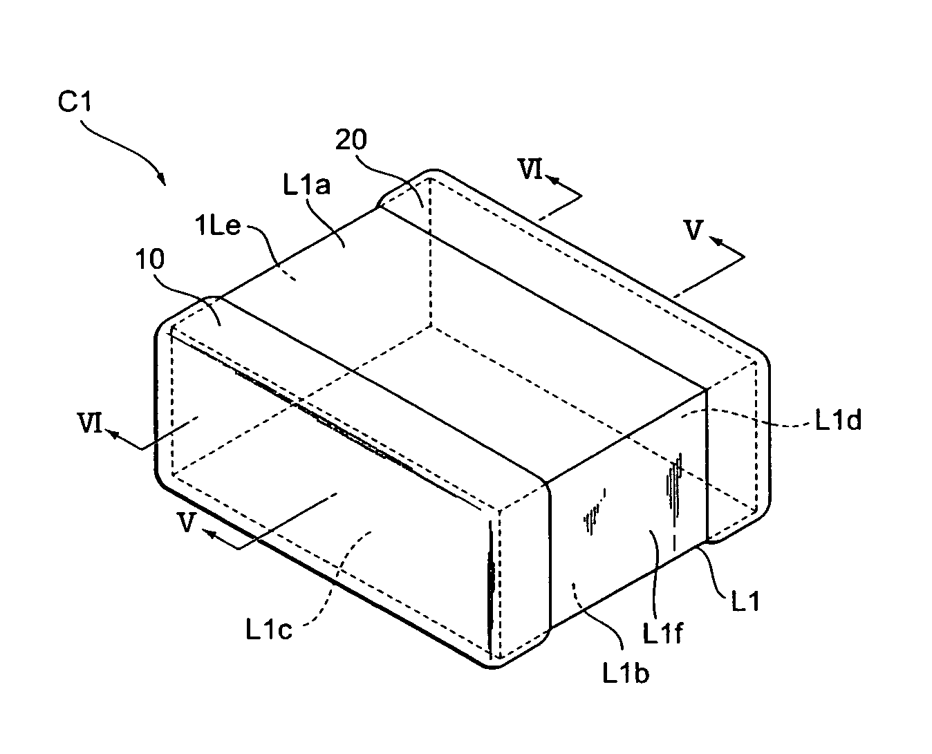
[0009]In the above-mentioned multilayer capacitor, the first inner electrodes are electrically connected to each other through the connecting conductor. The connecting conductor is covered with the insulator, and is electrically insulated from the first terminal electrode. Therefore, out of the plurality of first inner electrodes, only at least one first inner electrode further including the second lead portion is directly electrically connected to the first terminal electrode without the aid of other inner electrodes. As a result, the above-mentioned multilayer capacitor can enhance the equivalent series resistance. Further, the first and second terminal electrodes are respectively arranged on the first and second side faces extending in the longer side direction of the first and second main faces and opposing each other. Thus, in the above-mentioned multilayer capacitor, the distance between the first and second terminal electrodes becomes shorter, so that the current path in the multilayer capacitor becomes relatively short, whereby the equivalent series inductance can be made smaller. The above-mentioned multilayer capacitor is equipped with the insulator for covering the connecting conductor connecting with the first inner electrodes. Therefore, the above-mentioned multilayer capacitor can be mounted to a substrate or the like without taking account of the connecting relationship between the connecting conductor and land patterns, thus achieving versatility.
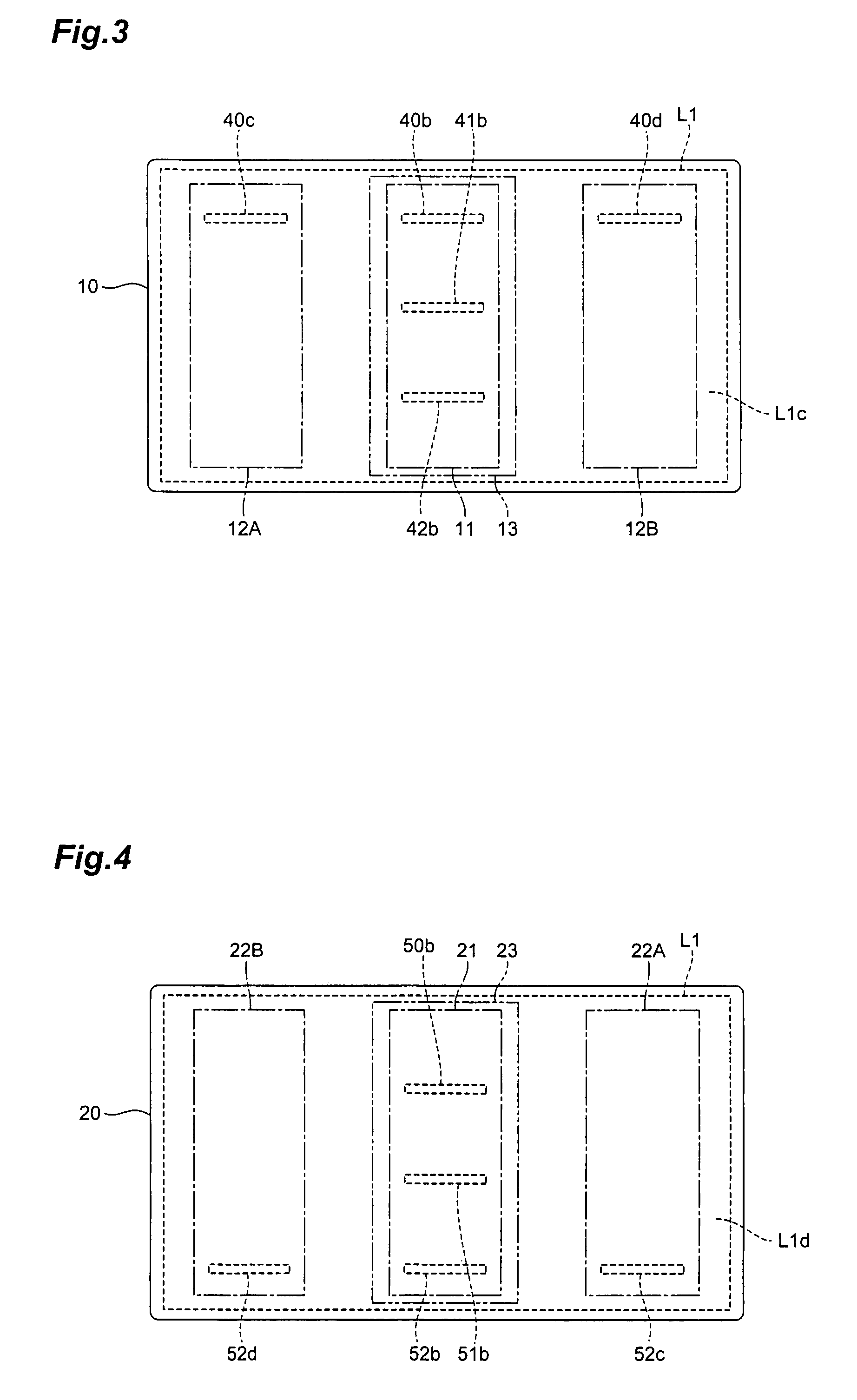
[0010]Preferably, the multilayer capacitor further comprises a base conductor mechanically connected to the end of the second lead portion of the at least one first inner electrode exposed to the first side face; wherein the base conductor is arranged between the first side face and first terminal electrode and covers the end of the second lead portion of the first inner electrode exposed to the first side face without overlapping the connecting conductor on the first side face. For example, when forming the connecting conductor by baking a metal material onto the first side face, this can favorably restrain the end of the second lead portion of the first inner electrode exposed to the first side face from oxidizing at the time of baking.
[0011]The present invention can provide a multilayer capacitor which can enhance the equivalent series resistance while keeping the equivalent series inductance from increasing.

Problems solved by technology

This has made it very difficult to suppress fluctuations in the power supply voltage under a tolerable level upon drastic changes in the load current, whereby a multilayer capacitor known as decoupling capacitor has come into connection with the power supplies.
However, the multilayer capacitor described in Patent Document 1 has no consideration for increasing the equivalent series resistance.

Method used


Image

  • Multilayer capacitor
  • Multilayer capacitor
  • Multilayer capacitor

Examples


Embodiment Construction

[0022]In the following, a preferred embodiment will be explained in detail with reference to the accompanying drawings. In the explanation, the same constituents or those having the same functions will be referred to with the same numerals while omitting their overlapping descriptions.

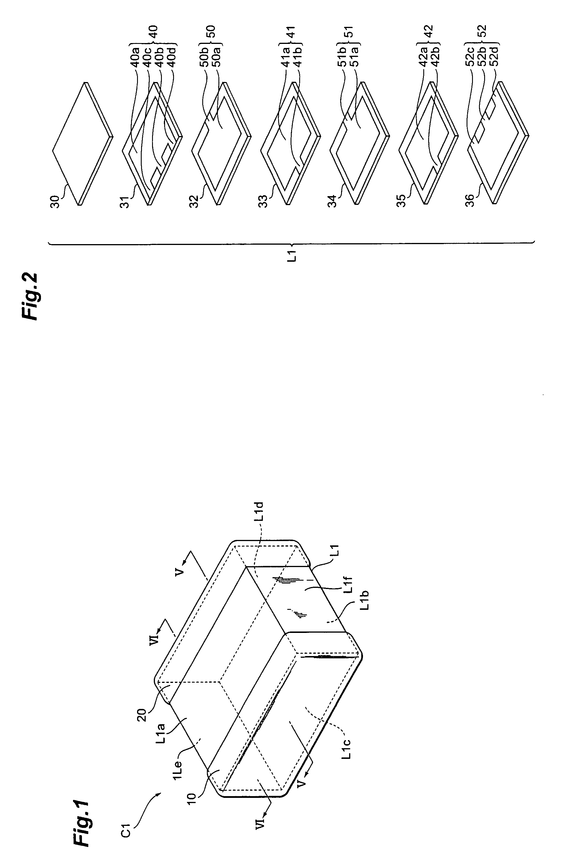
[0023]The structure of a multilayer capacitor C1 in accordance with the embodiment will be explained with reference to FIGS. 1 to 6. FIG. 1 is a perspective view of the multilayer capacitor in accordance with the embodiment. FIG. 2 is an exploded perspective view of the capacitor body included in the multilayer capacitor in accordance with the embodiment. FIG. 3 is a view for explaining the structure of connecting conductor, insulator, base conductors, and first terminal electrode arranged on a first side face of the multilayer capacitor in accordance with the embodiment. FIG. 4 is a view for explaining the structure of connecting conductor, insulator, base conductors, and second terminal electrode in ...


PUM


Abstract

A multilayer capacitor comprises a capacitor body, a first connecting conductor arranged on a first side face of the capacitor body, first and second terminal electrodes, and a first insulator arranged between the first connecting conductor and first terminal electrode. The capacitor body has a plurality of laminated insulator layers and a plurality of first and second inner electrodes. The second terminal electrode is connected to the second inner electrode. Each of the first inner electrodes has a first lead portion exposing an end to the first side face. At least one of the first inner electrodes also has a second lead portion whose end is exposed to the first side face. The first connecting conductor continuously covers all the ends of the first lead portions of the first inner electrodes and mechanically connects with the ends of the first lead portions. The first terminal electrode continuously covers the whole area of the first insulator and the ends of the second lead portions of the first inner electrodes exposed to the first side face, and is electrically connected to the second lead portions of the first inner electrodes.

Description

BACKGROUND OF THE INVENTION[0001]1. Field of the Invention[0002]The present invention relates to a multilayer capacitor.[0003]2. Related Background Art[0004]Known as this kind of multilayer capacitor is one comprising a rectangular parallelepiped capacitor body having a pair of oblong main faces opposing each other, a pair of side faces extending in a longer side direction of the pair of main faces so as to connect the pair of main faces to each other and opposing each other, and a pair of side faces extending in a shorter side direction of the pair of main faces so as to connect the pair of main faces to each other and opposing each other; and a plurality of terminal electrodes arranged on the pair of side faces extending in the longer side direction of the main faces; wherein the capacitor body has a plurality of insulator layers laminated in a direction in which the pair of main faces oppose each other, and a plurality of inner electrodes arranged such that each adjacent pair opp...

Claims


Application Information

Patent Timeline
Patent Type & Authority Patents(United States)
IPC IPC(8): H01G4/228
CPCH01G4/232H01G4/30H01G4/2325
Inventor TOGASHI, MASAAKIMATSUSHITA, YOSHITOMO
Owner TDK CORPARATION
Learn More