Small-sized low-power dissipation short-range radar that can arbitrarily change delay time between transmission and reception with high time resolution and method of controlling the same
a short-range radar, low-power dissipation technology, applied in the field of short-range radar, can arbitrarily change the delay time between transmission and reception with high time resolution, and control the same, and achieve the effects of low power dissipation, simple configuration, and high time resolution
- Summary
- Abstract
- Description
- Claims
- Application Information
AI Technical Summary
Benefits of technology
Problems solved by technology
Method used
Image
Examples
first embodiment
[0165]First, a configuration of a short-range radar according to a first embodiment of the present invention will be described.
[0166]FIG. 1 is a block diagram showing a configuration of a short-range radar 20 according to the first embodiment of the invention.
[0167]Specifically, the short-range radar 20 shown in FIG. 1 comprises a transmitter section 21, a receiver section 30, a trigger signal generating section 40, an analog-to-digital converter (ADC) 50, a signal processing section 51, and a control section 52.
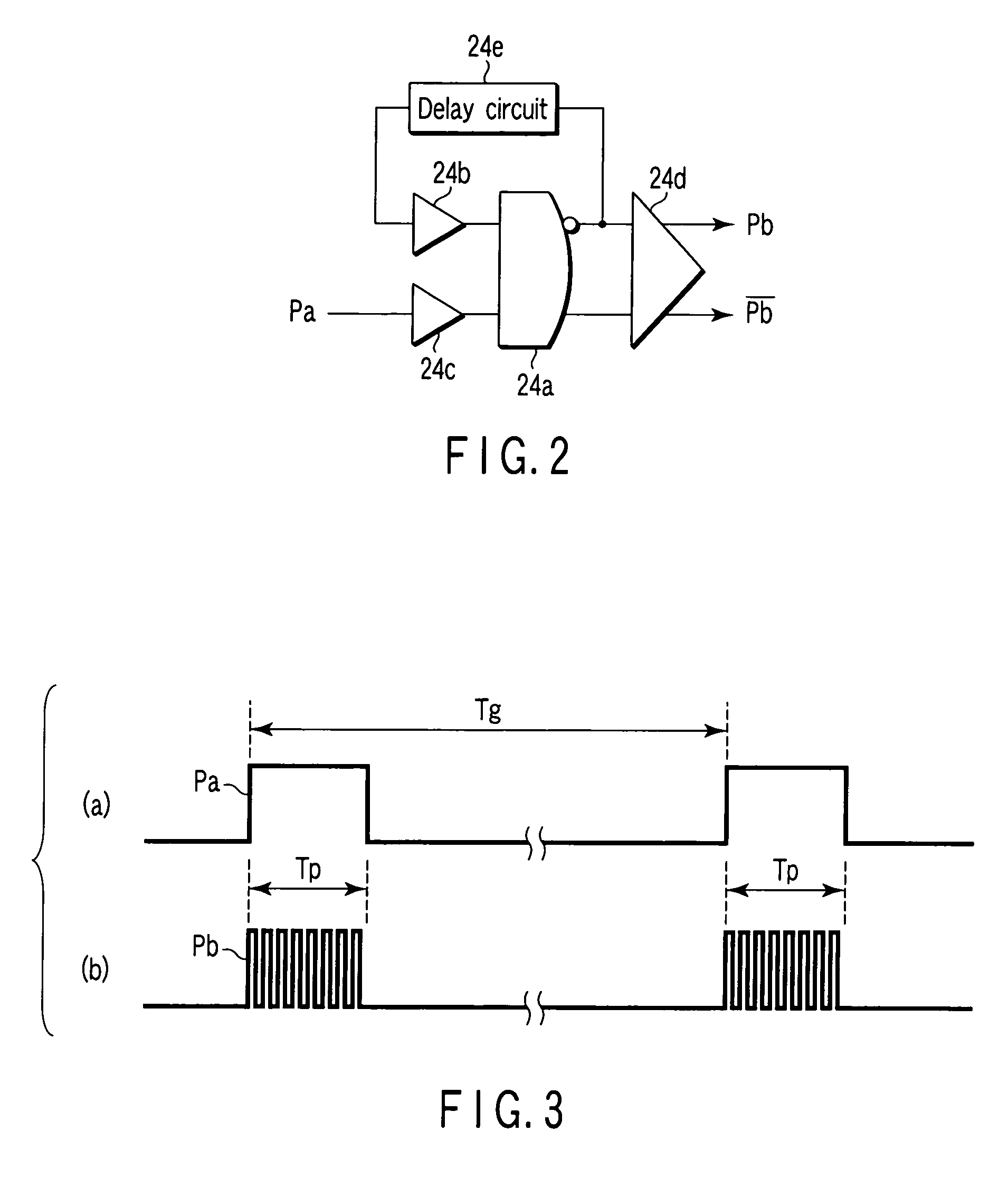
[0168]Each time receiving a trigger signal Gt output in a predetermined period Tg from the trigger signal generating section 40, the transmitter section 21 radiates via a transmission antenna 22 into space 1 a short pulse wave Pt having a predetermined carrier frequency Fc (e.g., 26 GHz) and a predetermined width Tp (e.g., 1 ns) generated as described later.
[0169]It is to be noted that the transmission antenna 22 is in some cases used together with a reception antenna 31 in ...
second embodiment
[0283]FIG. 13 is a block diagram showing a specific configuration of a trigger signal generating section 40′ as a configuration of important components of a short-range radar according to a second embodiment of the present invention.
[0284]In FIG. 13, the same components as those in the trigger signal generating section 40 according to the first embodiment shown in FIG. 7 are indicated by the same reference symbols, and explanation of them is omitted.
[0285]In the above-described first embodiment, the fixed delay circuit 43 is provided to reduce to zero a minimum value of delay time from a transmission timing to a reception timing.
[0286]However, if it is unnecessary to search an extremely short-distance region in a search range, it is also possible to omit the fixed delay circuit 43 and use as a transmission trigger signal Gt a first pulse P1 output from the first pulse generation circuit 42 as shown in FIG. 13.
[0287]By thus omitting the fixed delay circuit 43, an influence due to an ...
PUM
 Abstract
Description
Claims
Application Information
 - R&D
- Intellectual Property
- Life Sciences
- Materials
- Tech Scout
- Unparalleled Data Quality
- Higher Quality Content
- 60% Fewer Hallucinations
Browse by: Latest US Patents, China's latest patents, Technical Efficacy Thesaurus, Application Domain, Technology Topic, Popular Technical Reports.
© 2025 PatSnap. All rights reserved.Legal|Privacy policy|Modern Slavery Act Transparency Statement|Sitemap|About US| Contact US: help@patsnap.com


