
Ram air turbine blade disengagement mechanism for over-speed prevention

a technology of disengagement mechanism and air turbine blade, which is applied in the direction of rotors, marine propulsion, vessel construction, etc., can solve the problems of turbine blade release at very high speed, governor failure, damage to electric or hydraulic power equipment or control systems,

Active Publication Date: 2008-09-02
UNIGENE LABORATORIES +1
View PDF4 Cites 15 Cited by
  • Summary
  • Abstract
  • Description
  • Claims
  • Application Information

AI Technical Summary

Problems solved by technology

Failure of the turbine speed governor can cause an over-speed condition that may ultimately cause the release of a turbine blade at very high speed.
The most common cause of governor failure is due to seizure of the bearing between the turbine shaft and the governor yoke plate that controls the pitch of the turbine blades.
Should the wayward blade strike the aircraft fuselage, it may penetrate the skin and cause damage to electric or hydraulic power equipment or control systems.
It may also injure passengers or crew.
If one of the propulsion engines ingests the wayward blade, the engine may suffer severe damage that results in loss of thrust.
These methods no longer satisfy increasingly stringent certification and safety requirements promoted by airworthiness authorities.

Method used


Image

  • Ram air turbine blade disengagement mechanism for over-speed prevention
  • Ram air turbine blade disengagement mechanism for over-speed prevention
  • Ram air turbine blade disengagement mechanism for over-speed prevention

Examples


Embodiment Construction

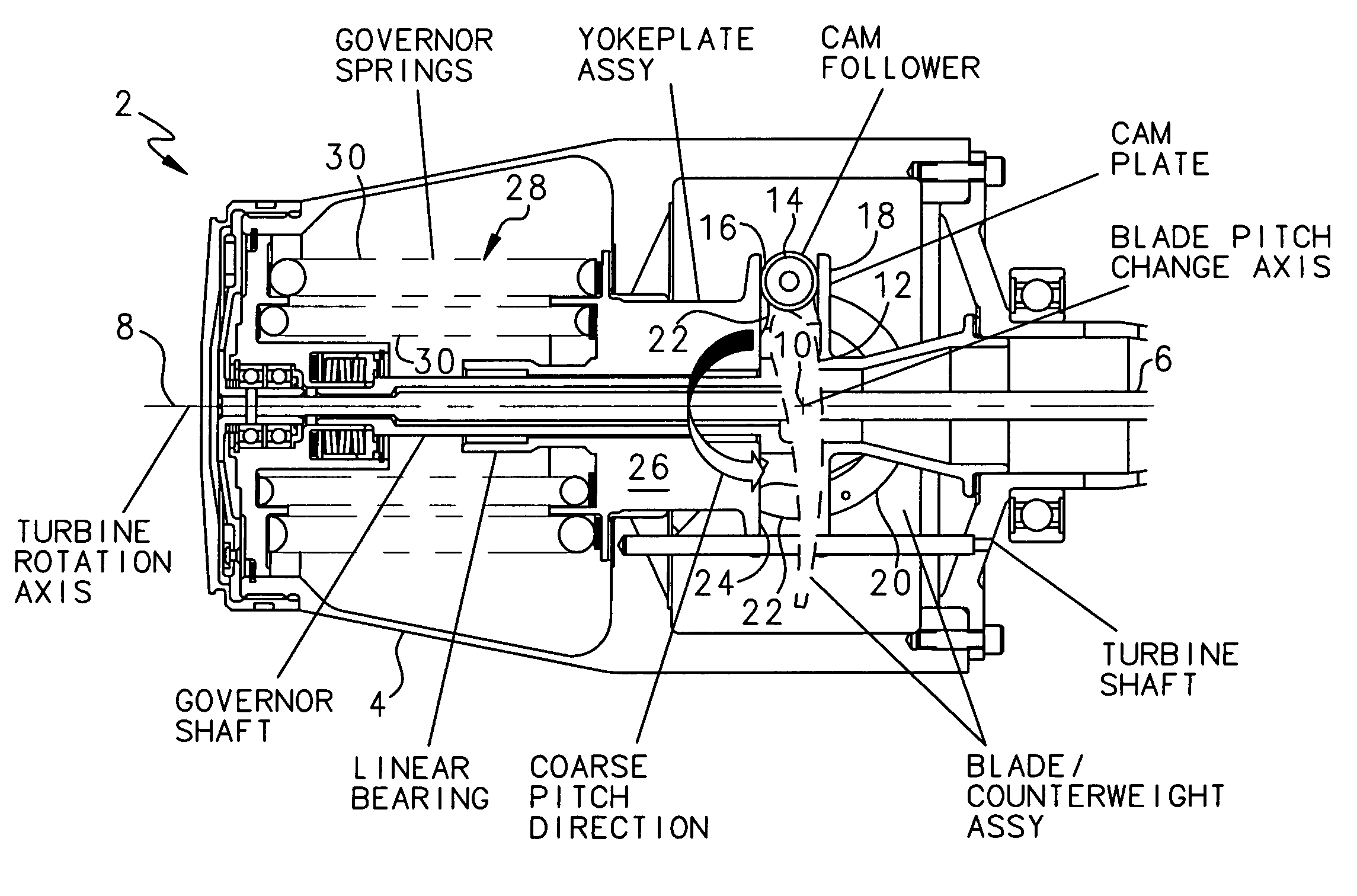
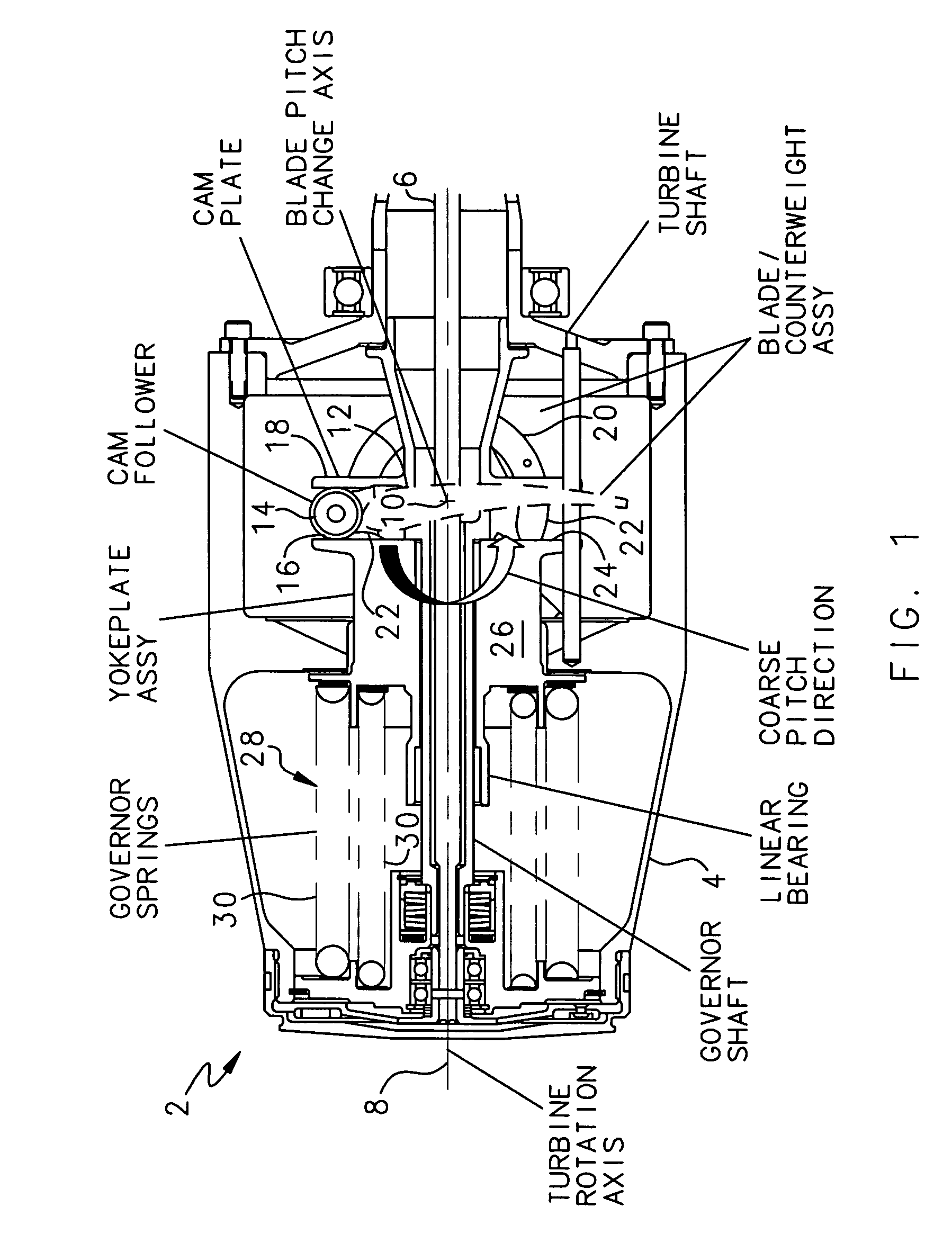
[0010]As described in Markunas et al., during normal operation RAT speed is controlled with a counterweight / spring governor balance system. As speed increases the centrifugal torque of a blade / counterweight assembly increases. This torque acts through a cam follower and yoke plate slidingly supported by a turbine shaft to compress a helical spring and thus change the position of the yoke plate. The yoke plate engages pins coupled to the blades that move the blades to a coarser angle with movement of the yoke plate and thus extract less power from the air stream. In this way, the turbine speed is controlled over a range of airspeeds, altitudes and loads.

[0011]Such a mechanical governor system requires a translation of rotary motion about the axis of the turbine shaft due to the blade / counterweight assembly turning about the blade pitch change axis to axial motion along the turbine shaft such that the force balance with the helical spring can be affected. The translation occurs by mea...


PUM


Abstract

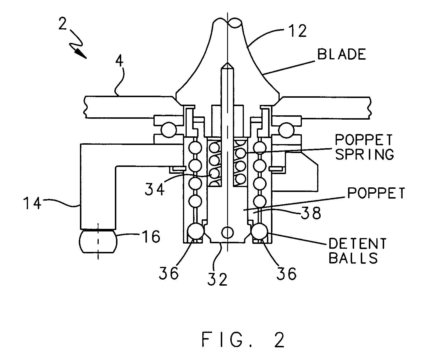
An improved ram air turbine (RAT) prevents release of its turbine blades due an over-speed condition by detecting an over-speed condition with a trigger mechanism and rotating the blades to a fixed coarse pitch position with a release mechanism.

Description

FIELD OF THE INVENTION[0001]The invention relates to emergency supplemental power supplies for aeronautical applications, and more particularly to an improved ram air turbine for generating emergency supplemental power for aircraft in flight.BACKGROUND OF THE INVENTION[0002]A ram air turbine (RAT) is a device for generating emergency supplemental power in a wide variety of aircraft. A RAT may generate hydraulic power, electric power or both. A RAT incorporates a turbine that extracts power from an air stream proximate the aircraft in flight. A typical RAT in current use is described in U.S. Pat. No. 4,743,163 to Markunas et al., owned by the assignee of this application, and incorporated herein by reference. The turbine is coupled to suitable power generating equipment, such as a hydraulic pump for hydraulic power and an electric generator for electric power.[0003]As described in Markunas et al., the turbine includes a speed governor that changes the turbine blade position to mainta...

Claims


Application Information

Patent Timeline
Patent Type & Authority Patents(United States)
IPC IPC(8): B64C11/00B64C27/00
CPCB64D41/007
Inventor NOHR, GARY D.SEIDEL, WILLIAM E.BANNON, DAVID G.RUSS, DAVID E.
Owner UNIGENE LABORATORIES
Learn More