
Test chart geometrical characteristic analysis system geometrical characteristic analysis method printer and ink-jet printer

a technology of geometrical characteristic analysis and test chart, which is applied in the direction of digital output to print units, instruments, image enhancement, etc., can solve the problems of image quality, marked deterioration in printing quality, and adjustment even by a skilled operator has the disadvantage of relying on the intuition of the operator, so as to prevent unintended interference and prevent unintended interference between marks

Inactive Publication Date: 2008-09-02
RISO KAGAKU CORP
View PDF91 Cites 14 Cited by
  • Summary
  • Abstract
  • Description
  • Claims
  • Application Information

AI Technical Summary

Benefits of technology

The solution allows for high-precision analysis of geometric properties with a simple and cost-effective procedure, reducing errors and improving the accuracy of geometric property analysis, thereby enhancing the quality of image recording and pickup processes.

Problems solved by technology

In particular, with the recording devices and the image pickup apparatuses employing plural recording units (e.g., heads) or plural image pickup units (e.g., CCDS) having a smaller area than the area of the recording area on the recording medium, recording of an image on a recording medium or image picking up is performed while relatively moving these units with respect to the recording medium, thus leading to a problem of the image quality by being greatly affected by geometric properties such as the positional relation between the plural recording units or between the plural image pickup units; the mechanical error during movement of these units; and so forth.
For example, with a color ink jet printer serving as a recording device including plural heads corresponding to various color inks, even slight deviation of the head position leads to failure in superimposition of dots in various colors in printing, leading to color shift, resulting in markedly deterioration in printing quality.
However, such a method wherein the operator checks the test chart for detecting deviation requires skill of the operator to a certain degree, and adjustment even by a skilled operator has the disadvantage of depending upon the intuition of the operator.
Furthermore, mechanical measurement of the head positions described above requires a precise mechanism, leading to high costs of installation of the measurement device, and high costs of maintenance after installation thereof, as well as high manufacturing costs due to the measurement, and leading to a problem of extra space for installation of the measurement device.
Furthermore, measurement of the dots or the lines through a microscope has the disadvantage of a narrow field of view of the endoscope, time consuming measurement, and a great deal of processing amount corresponding to the data amount taken by the measurement.
However, this leads to a new problem of deterioration in high-precision measurement due to substandard dot fixing, blot, irregularities in the dot impact position, or the like.

Method used


Image

  • Test chart geometrical characteristic analysis system geometrical characteristic analysis method printer and ink-jet printer
  • Test chart geometrical characteristic analysis system geometrical characteristic analysis method printer and ink-jet printer
  • Test chart geometrical characteristic analysis system geometrical characteristic analysis method printer and ink-jet printer

Examples


first embodiment

[0168]FIG. 6 through FIG. 32 show a first embodiment according to the present invention, wherein FIG. 6 is a block diagram which shows a configuration of a geometric property analyzing system.

[0169]The geometric property analyzing system according to the present embodiment comprises: a personal computer (PC) 5 serving as an analyzing device; a printer 6 serving as a recording device; a scanner 7 serving as an image pickup apparatus, as shown in FIG. 6.

[0170]The PC 5 comprises: a format storage unit 9 serving as format storage means for storing the geometric property format; a chart data creation / storage unit 8 including a chart data creating unit 10 for creating chart data (printed data) which is image data based upon the geometric property format read out from the format storage unit 9; a mark center calculating unit 12 for calculating the center position of each mark based upon the chart image output from an image pickup unit 17 described later; an analyzing unit 11 serving as ana...

third embodiment

[0321]On the other hand, with the present third embodiment, the marks are formed with different shapes, sizes, or the like, for each group, thereby having the advantage of allowing the operator to analyze the geometric properties using a monochrome sensor even in a case of substandard printing of the representative dots, regardless of the printer type such as a color printer or a monochrome printer.

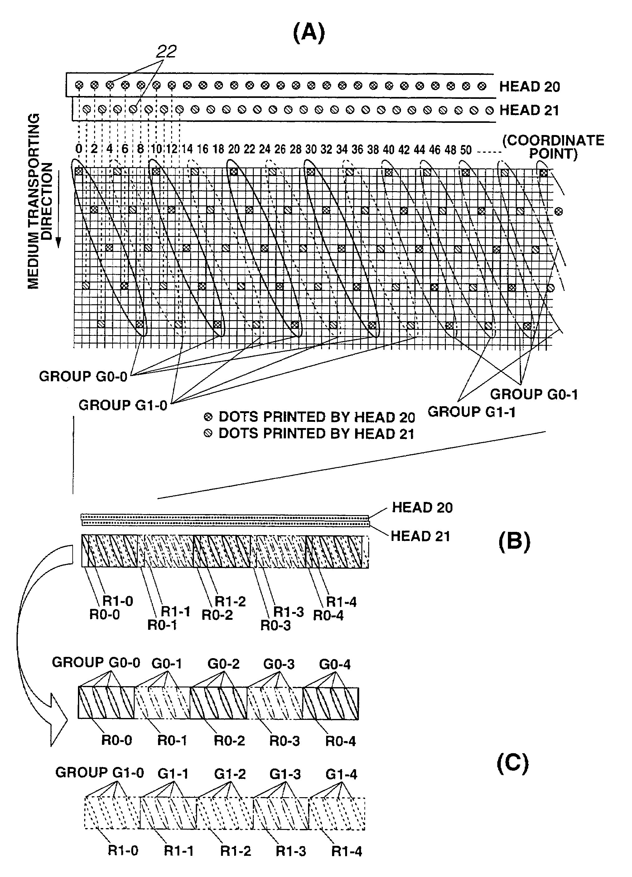
[0322]FIG. 37(A) shows the layout structure formed on the recording medium 1 according to the present embodiment, and FIG. 37(B) shows the layout structure thereof in further detail.

[0323]That is to say, the marks recorded in the test chart are classified into three groups of G0-0, G1-0, and G2-0, wherein the marks belonging to the group G0-0 are formed of two dots arrayed in the recording-medium-transporting direction as shown in FIG. 36(C), the marks belonging to the group G1-0 are formed of two dots arrayed in the line direction as shown in FIG. 36(B), and the marks belonging to the gr...

fourth embodiment

[0347]The geometric property analyzing system has a configuration wherein a recording medium on which a test chart is recorded, i.e., a recording medium on which printing is made, is transported through a transporting belt.

[0348]That is to say, the heads 30, 31, 32, and 33, and the image pickup unit 17 formed of a line sensor or the like, are arrayed along the direction for transporting the recording medium 1 on which printing is made, as shown in FIG. 33.

[0349]The recording medium 1 is transported through a transporting belt 41 formed of an endless belt. The transporting belt 41 also serves as a recording medium on which a mark group 42 formed of openings are formed (recorded) according to chart data.

[0350]A vacuum mechanism 43 serving as suctioning means which employs a suctioning pump is mounted at a reverse side of the belt face on which the recording medium 1 of the transporting belt 41 is closely contacted. The vacuum mechanism 43 suctions the recording medium 1 through the m...


PUM


Abstract

A format storage unit stores a predetermined geometric property format. A chart data creating unit creates chart data based upon the geometric property format, and a printing unit creates a test chart by printing mark groups on a recording medium such as a paper sheet based upon the chart data. An image pickup unit outputs a chart image by scanning the test chart, and a mark center calculating unit calculates the center of each mark based upon the chart image. A fitting unit performs a fitting calculation comparing calculation results output from the mark center calculating unit and the chart based upon the geometric property format such that the squared difference therebetween becomes minimum for each mark position.

Description

[0001]This application is a U.S. National Phase Application under 35 USC 371 of International Application PCT / JP03 / 03848 filed Mar. 27, 2003.TECHNICAL FIELD[0002]The present invention relates to: a test chart; a geometric property analysis system and a geometric property analysis method for analyzing geometric properties of at least one of a recording device, a recording medium, and an image pickup apparatus, using the test chart; and a printer and an ink jet printer having a function for analyzing the geometric properties using the geometric property analysis system and the geometric property analysis method.BACKGROUND ART[0003]When an image which has been recorded in a digital format is recorded onto a recording medium such as a paper sheet and film, or conversely when an image which has been recorded on a recording medium is picked up by an image pickup apparatus such as scanner or the like, the quality of those images are greatly affected by recording properties of the recording...

Claims


Application Information

Patent Timeline
Patent Type & Authority Patents(United States)
IPC IPC(8): B41J29/46B41J2/21G06T7/00H04N1/00H04N1/50
CPCB41J2/2135G06K9/036G06T7/0004G06T7/0006H04N1/506H04N1/00013H04N1/00015H04N1/00023H04N1/00031H04N1/00045H04N1/00002G06T2207/30144G06V10/993B41J29/46G06F3/12
Inventor TATSUTA, SEIJIEBIHARA, TOSHIYUKIKOMIYA, YASUHIROIOKA, KEN
Owner RISO KAGAKU CORP
Learn More