Casing unit for electronic device
a technology for electronic devices and casings, which is applied in the direction of electrical apparatus casings/cabinets/drawers, electrical apparatus construction details, and support structure mounting, etc., can solve the problems of difficult to improve the mounting density of printed circuit boards, difficult to miniaturize printed circuit boards, and difficult to mount electronic components in areas where strain occurs, so as to reduce stress in boards. , the effect of light weight and less strength
- Summary
- Abstract
- Description
- Claims
- Application Information
AI Technical Summary
Benefits of technology
Problems solved by technology
Method used
Image
Examples
first embodiment
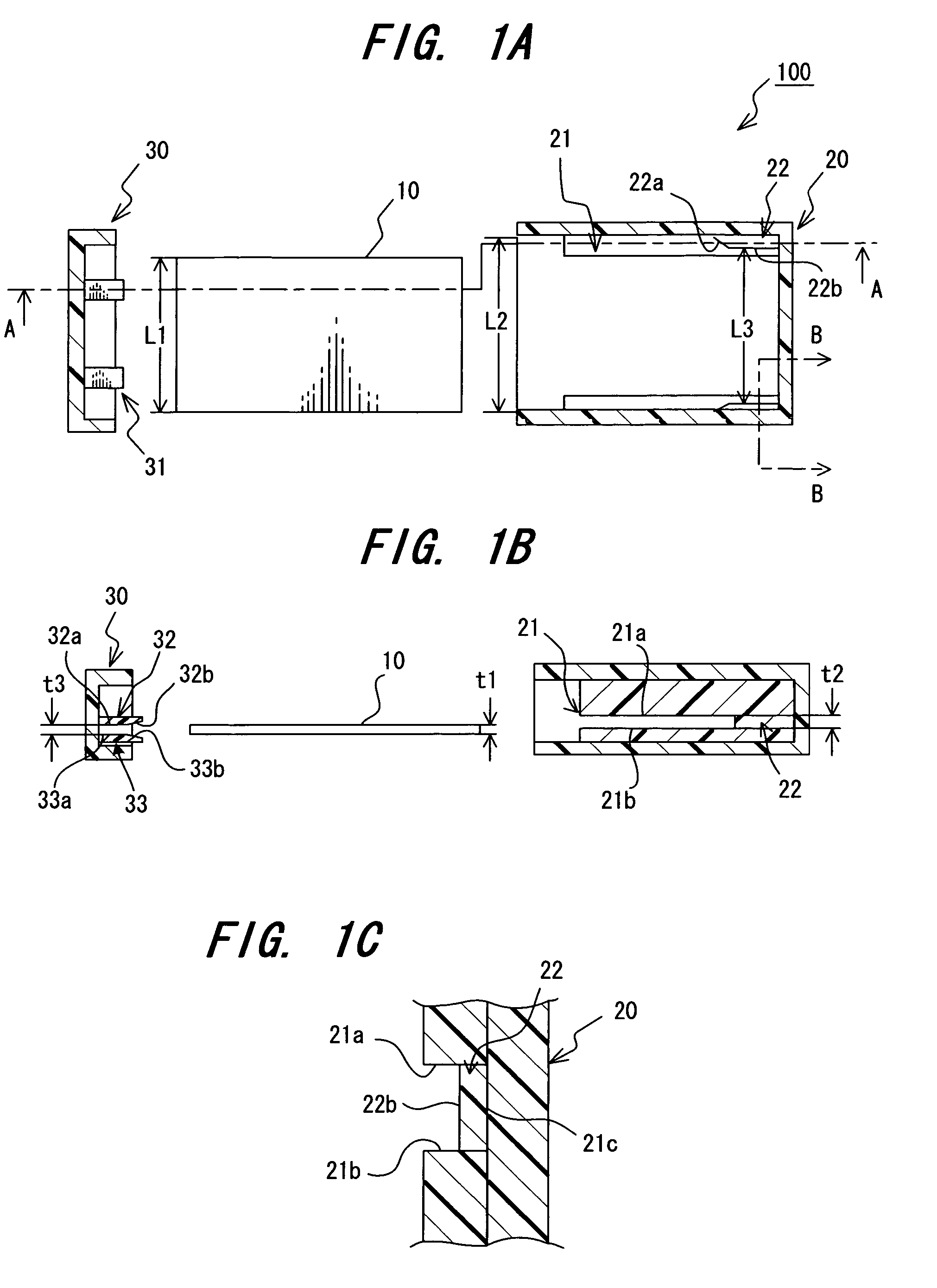
[0047]Referring to FIGS. 1A to 1C-2A to 2C, a casing unit for a casing unit for an electronic device will now be described. The electronic device, shown in conjunction with the present embodiment, is employed as an engine ECU (Electronic Control Unit) of a vehicle.
[0048]As shown in FIGS. 1A to 1C, the electronic device 100 with a casing unit according to the present embodiment is comprised of a printed circuit board 10, on which electronic component parts (not shown) are mounted, a case 20, in which the printed circuit board 10 is accommodated, and a cover 30 by which the case 20 is covered. The present embodiment has a characteristic feature in that the printed circuit board 20 is supported within the casing unit, composed of the case 20 and the cover 30, and the following description will be given with a focus on the case 20 and / or the cover 30.
[0049]The case 20 is formed of resin material (such as propylene) in a box-like configuration with one open end. Both side faces of the ca...
second embodiment
[0067]A second embodiment according to the present invention will now be described with reference to FIGS. 5A to 5C, in which the upper surface (21a) of the guide 21 is omitted in FIG. 5A.
[0068]The casing structure of the electronic device 100 of the second embodiment is mostly common in structure to the first embodiment and, so, a detailed description of common component parts is omitted with description made with a focus on differing points.
[0069]The second embodiment differs from the first embodiment in that second guide protruding members are provided on the case 20 with a view to positioning and fixing the printed circuit board 10 in a vertical direction thereof.
[0070]The electronic device 100 of the present embodiment includes the first guide protruding members 22 provided on the respective guides 21 of the case 20 as the component elements for permitting the printed circuit board 10 to be positioned and fixed in the planar direction thereof like the first embodiment. Also, th...
third embodiment
[0085]A third embodiment according to the present invention will now be described with reference to FIG. 6 and FIGS. 7A and 7B.
[0086]The casing structure of the electronic device 100 of the third embodiment is mostly common to that of the first embodiment and, so, description of the common component parts are herein omitted while description is made with a focus on differing component parts.
[0087]The third embodiment differs from the first embodiment in that a gap adjuster is provided on the cover 30 to position and fix the printed circuit board 10 in terms of the planar direction thereof.
[0088]In normal practice, the box-like case 20 is formed by injection molding or aluminum die-casting upon flowing component material under melted condition into a die-mold formed in a given configuration. When this takes place, in order to provide an increased stripping capability of the mold for the case 20 to be stripped off and provide improved durability of the mold, it has been a general prac...
PUM
 Abstract
Description
Claims
Application Information
 - R&D
- Intellectual Property
- Life Sciences
- Materials
- Tech Scout
- Unparalleled Data Quality
- Higher Quality Content
- 60% Fewer Hallucinations
Browse by: Latest US Patents, China's latest patents, Technical Efficacy Thesaurus, Application Domain, Technology Topic, Popular Technical Reports.
© 2025 PatSnap. All rights reserved.Legal|Privacy policy|Modern Slavery Act Transparency Statement|Sitemap|About US| Contact US: help@patsnap.com


