Coil array for magnetic resonance imaging with reduced coupling between adjacent coils

a magnetic resonance imaging and adjacent coil technology, applied in the field of imaging devices, can solve the problems that the whether during transmission or reception, cannot be excluded, and the mutual influence and coupling between adjacent coils cannot be excluded, so as to improve the resolution capability

Inactive Publication Date: 2008-08-26
RAPID BIOMEDIZINISCHE GERATE RAPID BIOMEDICAL
View PDF23 Cites 6 Cited by
  • Summary
  • Abstract
  • Description
  • Claims
  • Application Information

AI Technical Summary

Benefits of technology

[0006]The central object behind the invention is to further improve the resolution capability, which essentially determines the efficiency, of imaging processes according to the NMR principle. This object is achieved in that an electrical conductor is disposed at least in the area, is arranged within or outside the coil, completely surrounds said coil and is closed.
[0014]The adjacent coil are largely independent of one another and can thus operate at the smallest spacing from one another with the exclusion of mutual influences (transmitting and / or receiving). The proposed coil construction permits a considerable improvement of the signal / noise ratio. The resolution capability and the recording rate can thereby be increased.
[0021]In the second possible position, the shieldings of one coil overlap not only the shielding of the adjacent coil (as above), but also the coil itself, wherein the coils themselves do not mutually overlap. In the third possible position, the shielding and coil (conductor) of the two coils overlap one another completely. In a consideration of two arrangements, which each consist of a coil and the associated shielding and, as described in the most general case of the invention, only three defined spacings exist with a relative one-dimensional displacement, in which complete electromagnetic decoupling takes place. This does not take into account the fact that with a symmetrical arrangement further points arranged as mirror images exist. As a result, there is achieved a complete electromagnetic decoupling of adjacent coils, a precise assignment of the received signals to a defined coil and the possibility of denser packing of the fields (arrays). This results in an improvement of the signal / noise ratio.
[0026]The coil circuit is connected outwardly via a supply (during transmission) or via an evaluation unit (during reception). In particular operating modes, there is interest in deactivating particular coils, for example if a coil is to be used only for transmission or only for reception, or else if only individual coils are to be used in the work. For this event, it is proposed to short circuit the coil via a PIN diode. The name PIN is derived from the three regions of the diode (positive, intrinsic, negative) and is an externally switchable diode that is open in the operating state and renders the coil inactive on short circuiting. By means of the actuation, the action of the coil can be easily connected and disconnected.
[0027]In an advantageous development, the conductor acting as shielding can also be temporarily opened via a switch. On opening, the shielding effect is disconnected; in the case of a closed conductor, on the other hand, the shielding is connected. In particular operating states, for example during transmission, it is advisable to render the shielding inactive to avoid energy losses by disconnect it in the above-described manner. A further advantage consists in the fact that, in the inactive operating state, that is to say with a disconnected coil, a further disconnection of the shielding offers the decisive advantage of avoiding distortion of the magnetic field. The constructional implementation of the temporary opening or closing of the conductor is in principle free within the scope of the invention. In a similar manner to the coil, bridging can be carried out with a switchable diode, which performs the connecting and closing of the diodes in the conducting direction. Actuation is possible by the use of PIN diodes.

Problems solved by technology

However, the last requirement has the decisive disadvantage that mutual influences and couplings between adjacent coils, whether during transmission or reception, cannot be excluded.

Method used


Image

  • Coil array for magnetic resonance imaging with reduced coupling between adjacent coils
  • Coil array for magnetic resonance imaging with reduced coupling between adjacent coils
  • Coil array for magnetic resonance imaging with reduced coupling between adjacent coils

Examples


Embodiment Construction

[0011]The mode of operation is as follows:

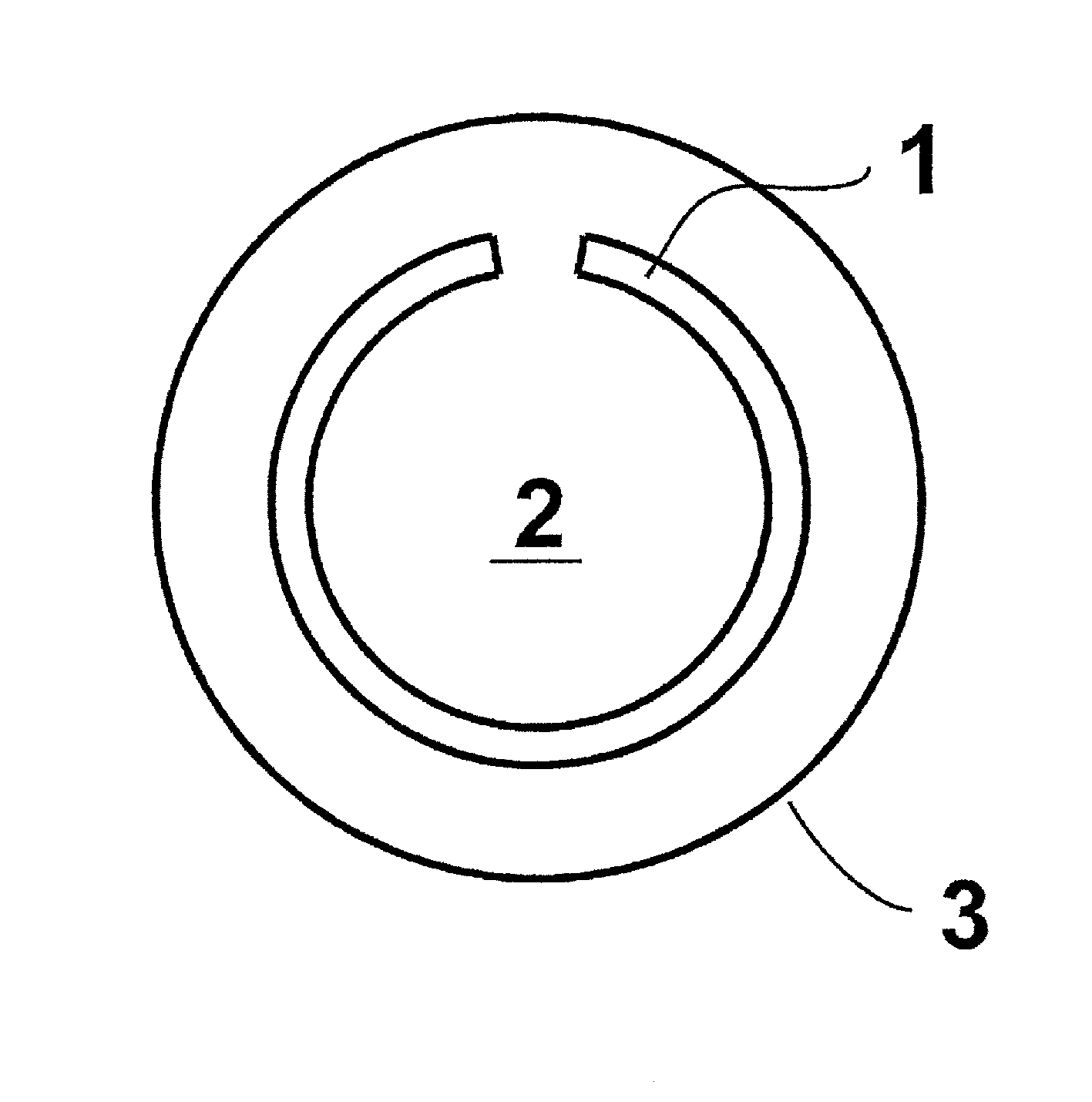
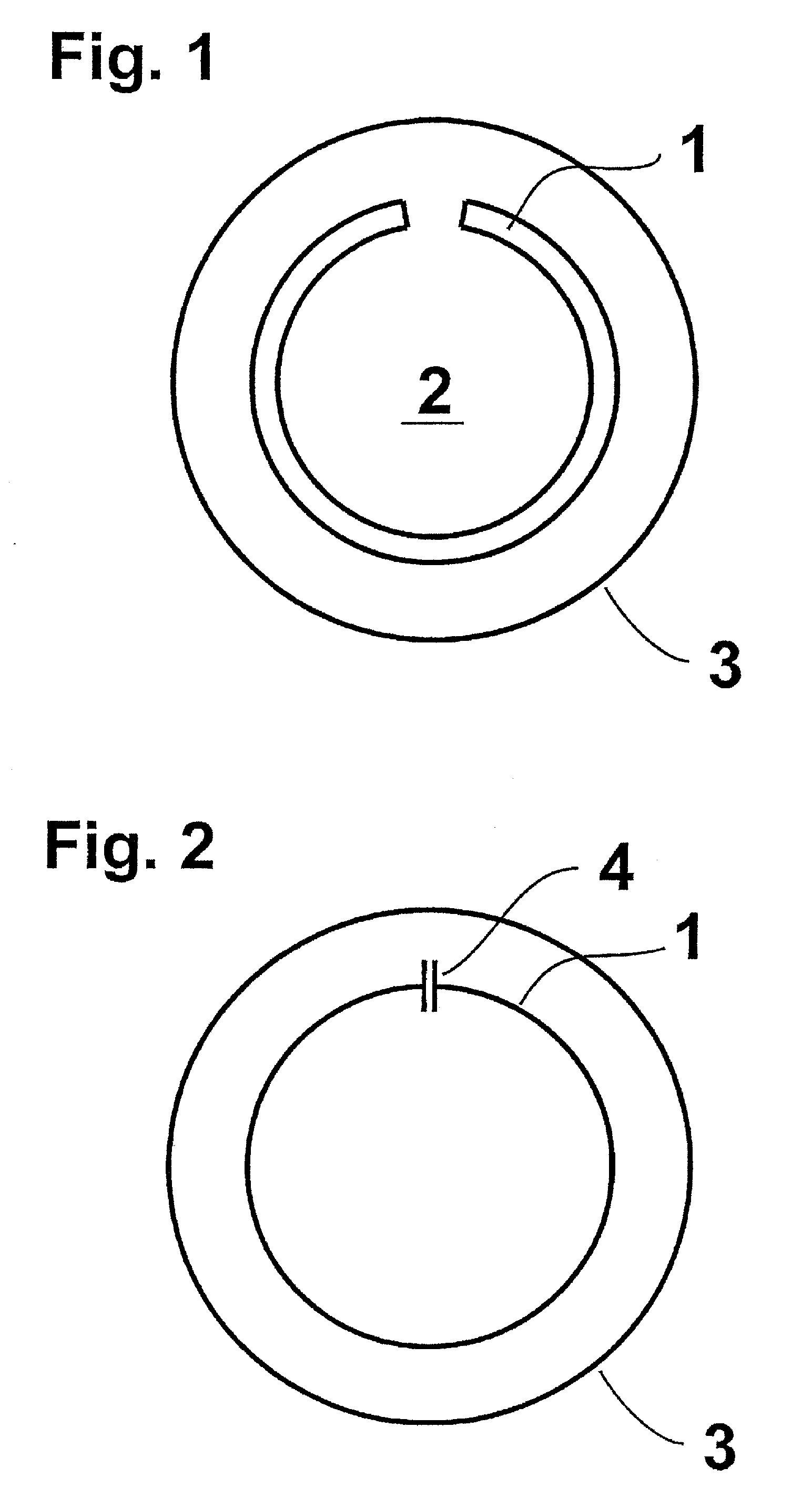
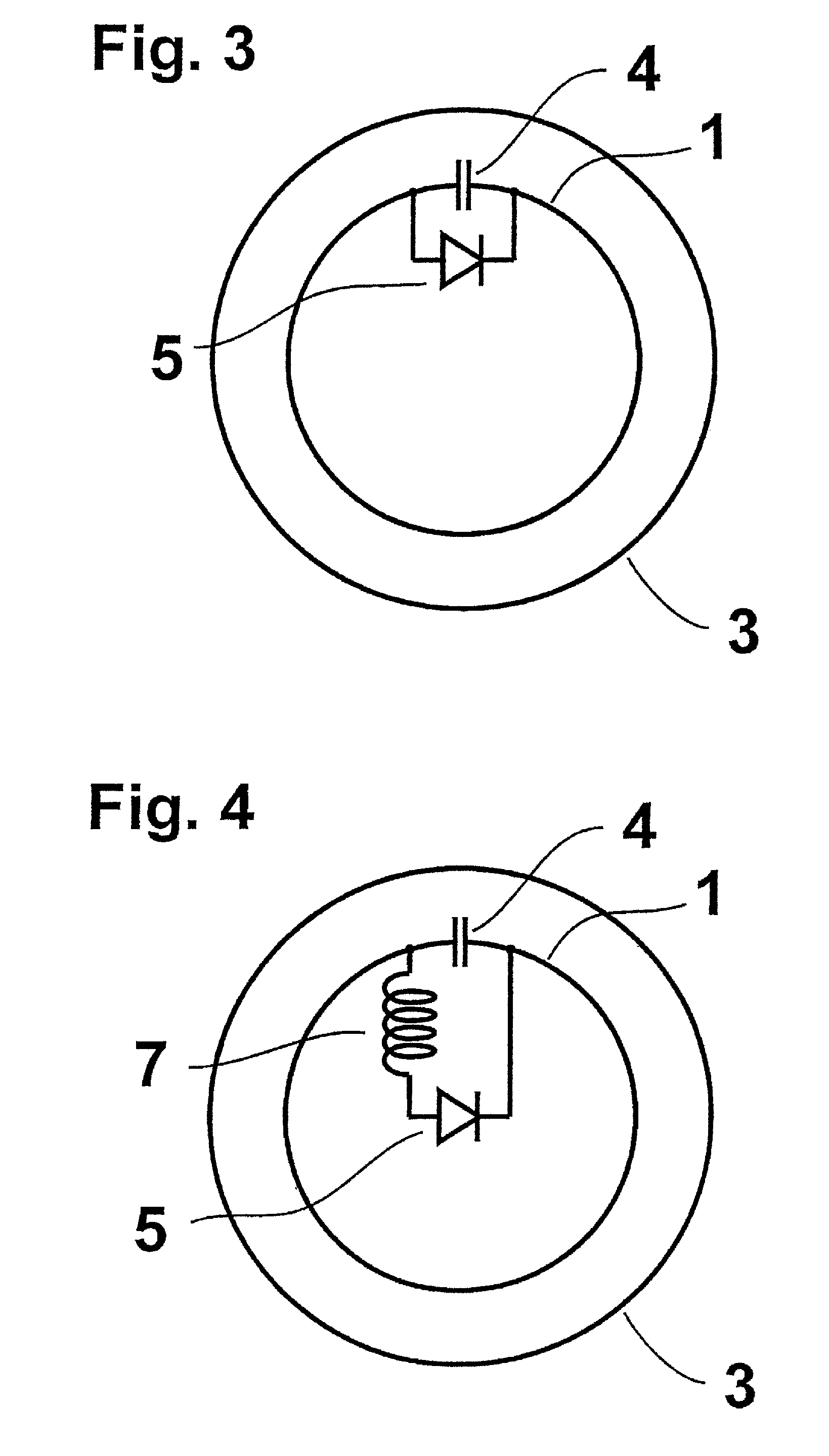
[0012]In a manner known per se, the coil transmits and / or receives the corresponding radio frequencies essentially perpendicular to the area described by the coil. The surrounding and closed conductor that is additionally applied acts as a shield against both electrical and magnetic fields. The surrounding electrical fields terminate at the conductor, which wards off electrical fields in the manner of a Faraday's cage. The impingement of the magnetic alternating fields additionally effects the development of eddy currents, which, according to Lenz's law, are opposite in direction to the magnetic current generating the eddy currents and thus contribute compensating them. As a result, there follows both electrical and magnetic shielding.

[0013]By virtue of the arrangement of the conductor in the area of the coil, a shielding essentially in this direction is effected, so that the transmission and / or reception of signals, which are emitted and / or...


PUM


Abstract

A coil array for an imaging apparatus using nuclear magnetic resonance (NMR) for the transmission or reception, or both, of the Lamor frequency signals, assembled in fields, or arrays, includes individual coils made from a conductor track that defines an area. An electrical conductor is applied, at least in the defined area, and is arranged either within or outside the individual coils, and completely surrounding the individual coils and forming a closed circuit.

Description

BACKGROUND OF THE INVENTION[0001]1. Technical Field of the Invention[0002]The invention relates to an imaging device for use in nuclear magnetic resonance (NMR) using coils that serve for the transmission and / or reception of the frequency signals (Larmor frequency) and which are assembled in fields (arrays), the individual coil comprising a conductor track, which defines an area.[0003]2. Description of the Prior Art[0004]Nuclear magnetic resonance has found widespread use as an important imaging process. Therein, the effect is utilized that atoms in a homogeneous magnetic field, when supplied with energy by means of electromagnetic waves of particular frequencies, undergo excitation by virtue of the absorption. The frequency here is determined from the intensity of the constant magnetic field and the special characteristic properties of the nucleus. After a short time, the excited spin returns to its ground state, that is to say to the lowest energy state, and emits an electromagnet...

Claims


Application Information

Patent Timeline
IPC IPC(8): G01V3/00G01R33/3415G01R33/36G01R33/422
CPCG01R33/3415G01R33/422G01R33/365
Inventor LANZ, TITUSGRISWOLD, MARK
Owner RAPID BIOMEDIZINISCHE GERATE RAPID BIOMEDICAL
Why Eureka
Try Eureka