
Control circuit for an actuator

a control circuit and actuator technology, applied in electrical control, magnetic bodies, piezoelectric/electrostrictive device details, etc., can solve problems such as significant interferen

Inactive Publication Date: 2008-08-26
ROBERT BOSCH GMBH
View PDF9 Cites 2 Cited by
  • Summary
  • Abstract
  • Description
  • Claims
  • Application Information

AI Technical Summary

Benefits of technology

The solution effectively suppresses electromagnetic interference by damping differential currents and reducing resonance effects, ensuring compliance with electromagnetic emission limits and minimizing interference in electronic systems within the engine compartment.

Problems solved by technology

In this instance, the very low-resistance connection between the engine block, the vehicle body, and the control unit is particularly disadvantageous, due to which, together with the parasitic capacitances and possibly parasitic inductances making the interference currents possible, a high-quality resonance circuit is formed.
The electromagnetic oscillations arising in the resonance circuit result in significant interference, for example, in radio receiver systems of a motor vehicle containing the control circuit or also in further electronic systems.

Method used


Image

  • Control circuit for an actuator
  • Control circuit for an actuator
  • Control circuit for an actuator

Examples


Embodiment Construction

[0027]FIG. 5 illustrates an internal combustion engine 1 of a motor vehicle, in which a piston 2 is movable back and fourth in a cylinder 3. Cylinder 3 is provided with a combustion chamber 4, which, inter alia, is delimited by piston 2, an inlet valve 5, and an exhaust valve 6. An intake manifold 7 is coupled to inlet valve 5 and an exhaust pipe 8 is coupled to exhaust valve 6.

[0028]A fuel injector 9, via which fuel may be injected into combustion chamber 4, projects into combustion chamber 4 in the area of inlet valve 5 and exhaust valve 6. A catalyst 12 is housed in exhaust pipe 8, which is used for purifying the exhaust gases resulting due to the combustion of the fuel.

[0029]Fuel injector 9 is connected via a high-pressure line to a fuel accumulator 13. In a similar manner, the fuel injectors of the other cylinders of internal combustion engine 1 are also connected to fuel accumulator 13. Fuel accumulator 13 is supplied with fuel via a supply line. A, for example, mechanical, fu...


PUM

PropertyMeasurementUnit
parasitic capacitancesaaaaaaaaaa
timeaaaaaaaaaa
peak-to-peak voltageaaaaaaaaaa

Abstract

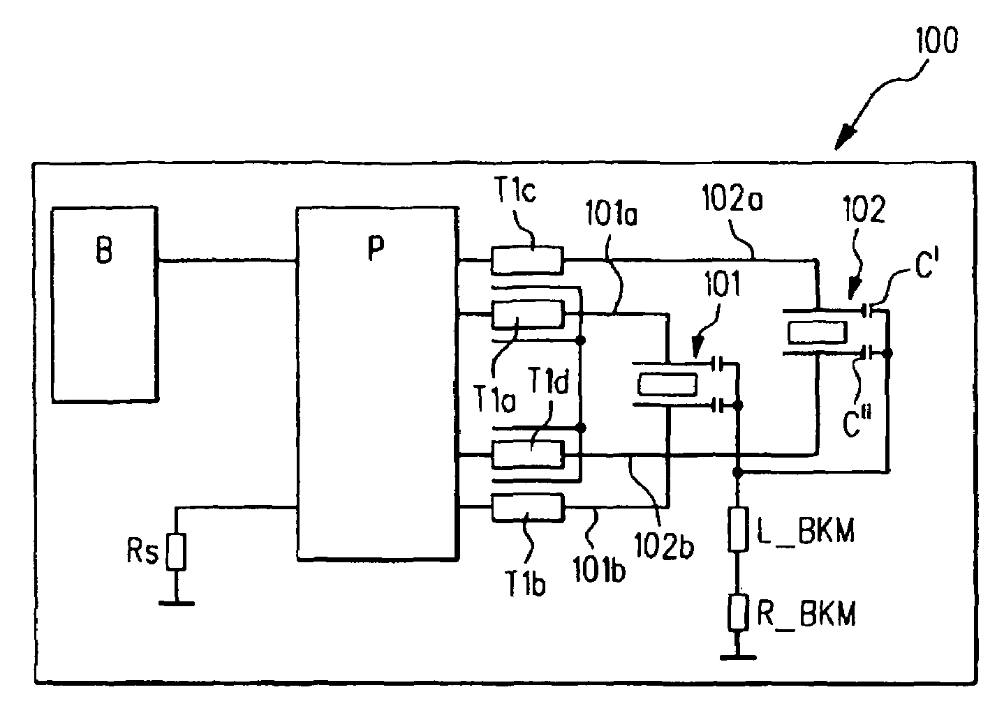
In a control circuit for at least one actuator, in particular for a capacitive actuator of an injection system of an internal combustion engine, a control current can be applied to the actuator.The control circuit has an inductor, e.g., having a core and having multiple windings, the windings being designed and connected to the control circuit such that a control current flowing into the actuator and a control current flowing out of the actuator each flow through different windings of the inductor, and a magnetic flux induced in the inductor or its core by the control current flowing into the actuator and a magnetic flux induced in the inductor or its core by the control current flowing out of the actuator mutually compensate one another.

Description

FIELD OF THE INVENTION[0001]The present invention relates to a control circuit for at least one actuator, e.g., for a capacitive actuator of an injection system of an internal combustion engine, in which a control current can be applied to the actuator.[0002]Furthermore, the present invention relates to an injection system for an internal combustion engine and to an internal combustion engine.BACKGROUND INFORMATION[0003]Typical control circuits of the above-mentioned type are used, for example, for activating piezoelectric elements which act on a valve needle of a fuel injector, for example, in order to cause fuel injection into a combustion chamber of the internal combustion engine.[0004]In order to achieve a stroke of the piezoelectric element which is sufficient for activating the valve needle, in conventional systems a control voltage of 160 V or more must be applied, which is typically clocked, in order to achieve controlled opening of the fuel injector and avoid damage to the ...

Claims


Application Information

Patent Timeline
Patent Type & Authority Patents(United States)
IPC IPC(8): H01H47/00H01F13/00H10N30/80F02D41/20H10N30/20
CPCH02N2/067F02D41/2096
Inventor REINEKE, JOERGWIEDERGUT, ARMINSCHWEIGER, KARLFARKAS, KARLSCHMIDT, KARL-HEINZ
Owner ROBERT BOSCH GMBH
Learn More