Electromagnetically actuated drives for linear motion

An electromagnetic drive, electromagnet technology, applied in the direction of the electromagnet with armature, valve operation/release device, electromagnet, etc., can solve the problem of large size, can not provide high-voltage system, etc., to achieve the effect of strong damping

Active Publication Date: 2020-05-19
VOITH PATENT GMBH
View PDF5 Cites 0 Cited by
  • Summary
  • Abstract
  • Description
  • Claims
  • Application Information

AI Technical Summary

Problems solved by technology

However, the size of this drive is relatively large
Smaller drive units in the prior art cannot provide the force required for high pressure systems to raise and lower the shaft, with sufficient power reserve to prevent potential contamination from penetrating the pressure medium

Method used


Image

  • Electromagnetically actuated drives for linear motion
  • Electromagnetically actuated drives for linear motion
  • Electromagnetically actuated drives for linear motion

Examples


Embodiment Construction

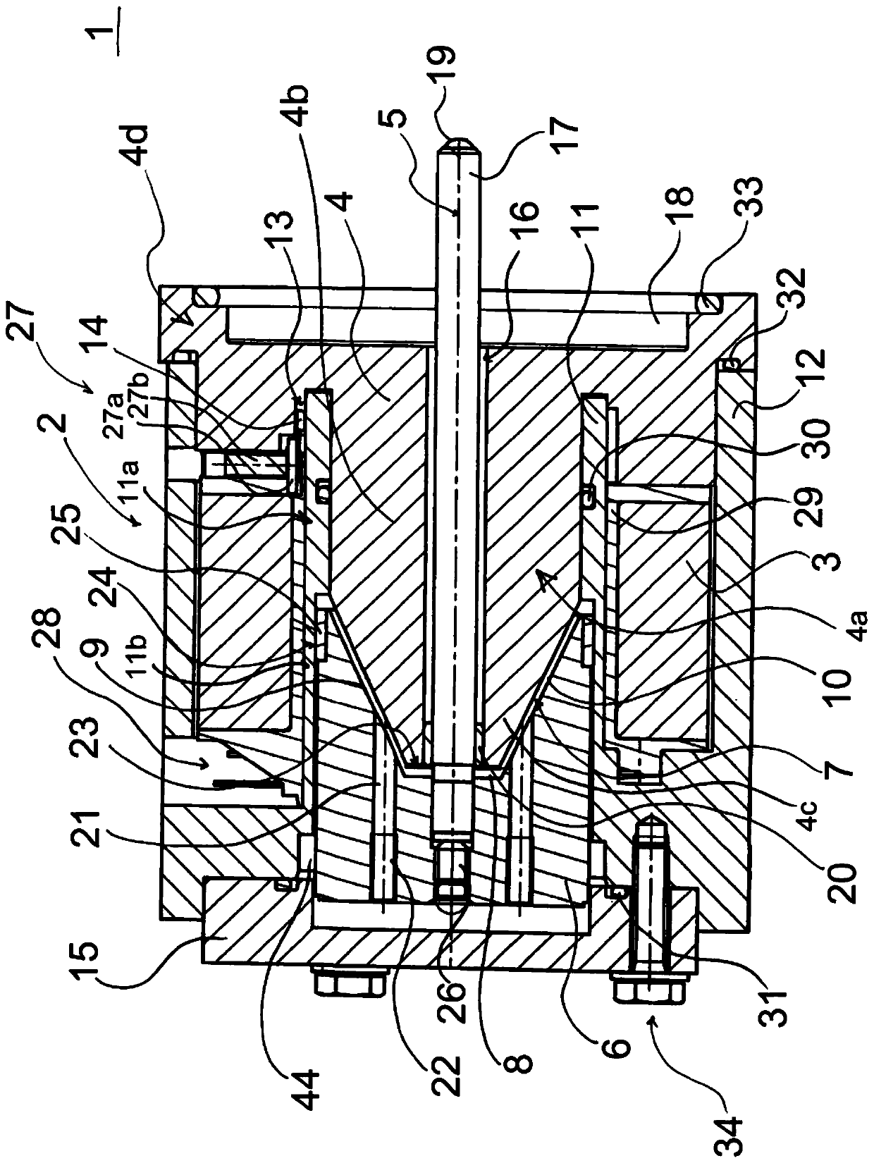
[0039] figure 1 A sectional view of an electromagnetic drive 1 according to the invention is shown and has an electromagnet 2 with a coil 3 , a core 4 and an armature 6 . Between the core 4 and the armature 6 an air gap 7 is formed, which is defined by the surface of the frusto-conical or conical core 4 and the diametrically oppositely shaped surface of the armature 6 .

[0040] The housing 12 of the electromagnetic drive 1 is rectangular, wherein the housing 12 has a hollow cylindrical rod 11 inside. The rod 11 and the housing 12 are integrally formed, especially integrally rotatable. Furthermore, the rod 11 is open to both the upper side as well as the lower side of the housing 12 and thus forms a channel between the two opposite sides.

[0041] The core 4 has a rotationally symmetrical body 4 a relative to the axis of symmetry 5 with a cylinder 4 b and a frustum 4 c inserted into the cylindrical interior of the rod 11 . In order to mount or fix the core 4 at a specific p...


PUM


Abstract

The invention relates to an electromagnetic driving device (1), which is used to realize linear motion, and the electromagnetic driving device (1) comprises a coil (3), a core (4) and an armature (6) The electromagnet (2), the armature (6) can move linearly along the axis of symmetry (5) of the core (4), wherein between the core (4) and the armature (6) An air gap (7) is formed between them. In order to provide a simple, compact, cost-effective and flexible application of electromagnetic drives in high pressure systems, and to precisely position the piston at any given position at an optimized extension speed, the air gap (7) has a base (8) and two branches (9, 10), said branches (9, 10) extending symmetrically with respect to said axis of symmetry (5), and said air gap (7) being substantially frusto-conical in longitudinal section and said branches (9, 10) are arranged to form an included angle α with respect to said axis of symmetry (5) of said core (4).

Description

technical field [0001] The present invention relates to an electromechanical transducer, in particular, an electromagnetically actuated drive for achieving linear motion. Background technique [0002] Among other uses, electromagnetic drives are used to actuate hydraulic spool valves, especially for the opening and closing of valves. In this respect, a distinction is made between low-pressure systems in the range of 3-25 bar, medium-pressure systems in the range of 25-65 bar and high-pressure systems in the range of 65-200 bar. In the prior art, hydraulic valves are known as low pressure systems in the range of about 10 bar. Actuation drives for valves in low pressure systems are larger and heavier than those used in high pressure systems. [0003] From a cost point of view as well as from a technical point of view, there is an increasing need for new drives for high-pressure systems with smaller valves. High pressure systems have the advantage of using fluids with lower ...

Claims


Application Information

Patent Timeline
Patent Type & Authority Patents(China)
IPC IPC(8): F16K37/00F16K31/06H01F7/08H01F7/16
CPCF16K31/0675F16K37/0041H01F7/081H01F7/088H01F7/1607H01F2007/086H01F2007/163H01F2007/1661H01F7/16
Inventor A·戈尔S·莱曼S·林多尔非尔
Owner VOITH PATENT GMBH
Why Eureka
Try Eureka