
Unstable optical resonator and laser device

a laser device and optical resonator technology, applied in the direction of laser details, optical resonator shape and construction, active medium materials, etc., can solve the problem that the resonator is unstable in all directions, and achieves the effect of small gain, easy adjustment, and large cross section

Active Publication Date: 2008-08-19
DEUTSCHES ZENTRUM FUER LUFT & RAUMFAHRT EV
View PDF18 Cites 3 Cited by
  • Summary
  • Abstract
  • Description
  • Claims
  • Application Information

AI Technical Summary

Benefits of technology

The invention provides a resonator that can be used for optically active media with small gain and large cross section. The resonator uses spherical mirrors and an asymmetrical outcoupling, which prevents high-mode coupling and creates a more stable mode with reduced structure in the far field. The resonator is easier to adjust and is less sensitive to changes in mirror radii and tiltings. It can be used with any medium cross section and can be optimized for a specific medium. The resonator provides a more compact outcoupling surface and a more symmetrical intensity distribution in the far field. The resonator can be used for both gas and solid-state optically active media. The asymmetrical outcoupling can be achieved by shaping the mirror or influencing the beam path. The resonator is advantageous for large cross section media and can be easily adjusted for optimal performance.

Problems solved by technology

This resonator is, in turn, unstable in all directions.

Method used


Image

  • Unstable optical resonator and laser device
  • Unstable optical resonator and laser device
  • Unstable optical resonator and laser device

Examples


first embodiment

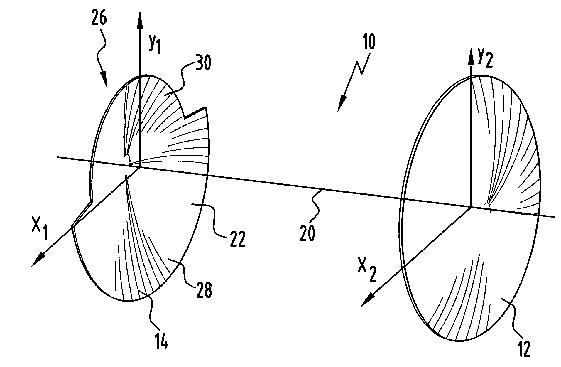
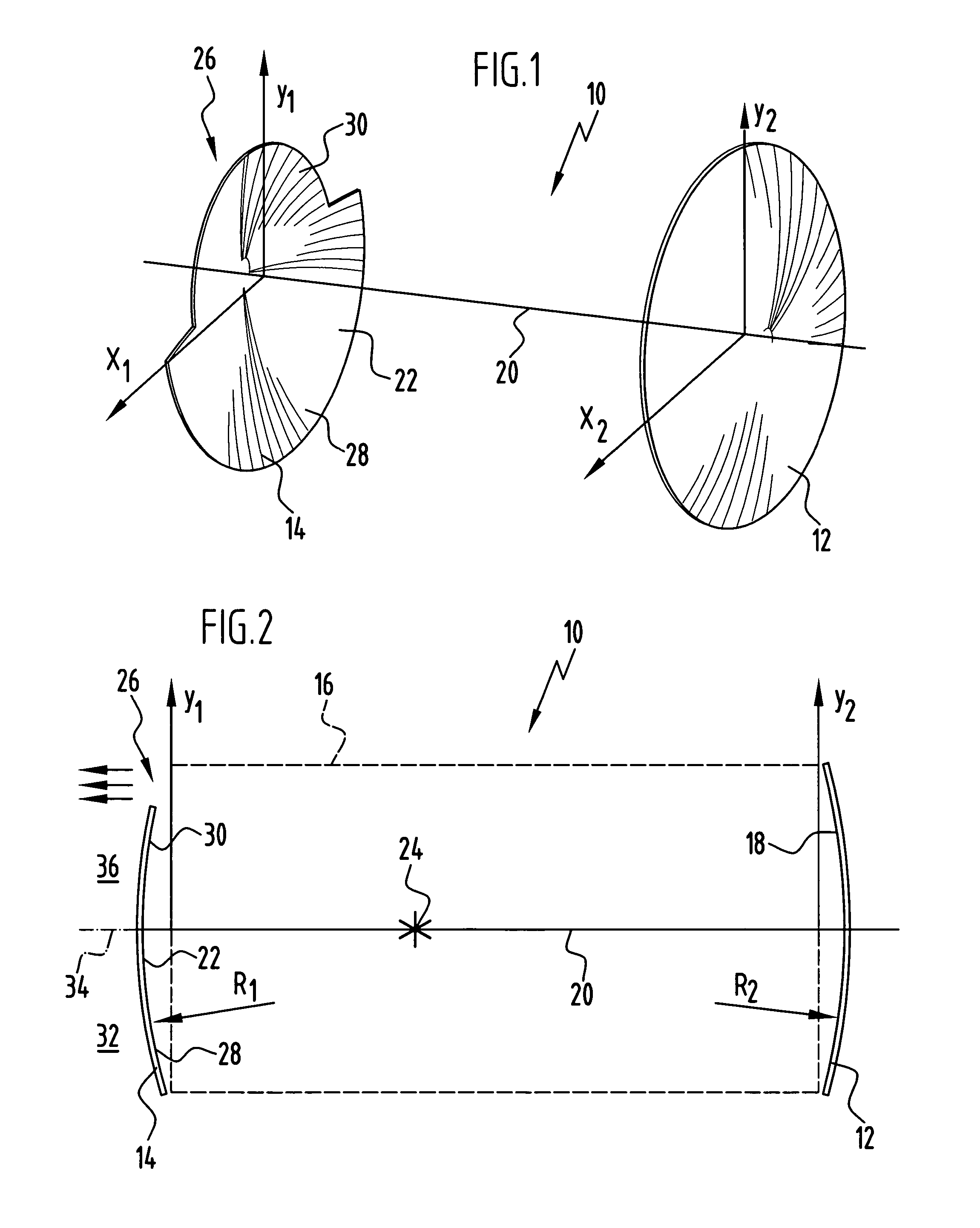
[0035]an unstable optical resonator according to the invention, which is shown in FIGS. 1 and 2 and is generally designated therein by reference numeral 10, comprises a back mirror 12 and an outcoupling mirror 14. The two mirrors 12 and 14 are spaced from each other, and the optically active medium 16 is arranged or guided between these mirrors. In particular, in the case of a gas laser, a receptacle, which accommodates the optically active medium, or a flow space, through which the optically active medium flows, is arranged between the mirrors 12, 14. Such a receptacle or container is shown in FIG. 7 and designated therein by the reference numeral 70. A flow space 84 is shown in FIG. 8.

[0036]The back mirror 12 is of spherical design with a concave surface 18, which faces the optically active medium 16. This concave surface 18 has a certain radius R2. The concave surface 18 lies on the surface of an imaginary sphere, and the radius is measured with respect to the center point of the...

second embodiment

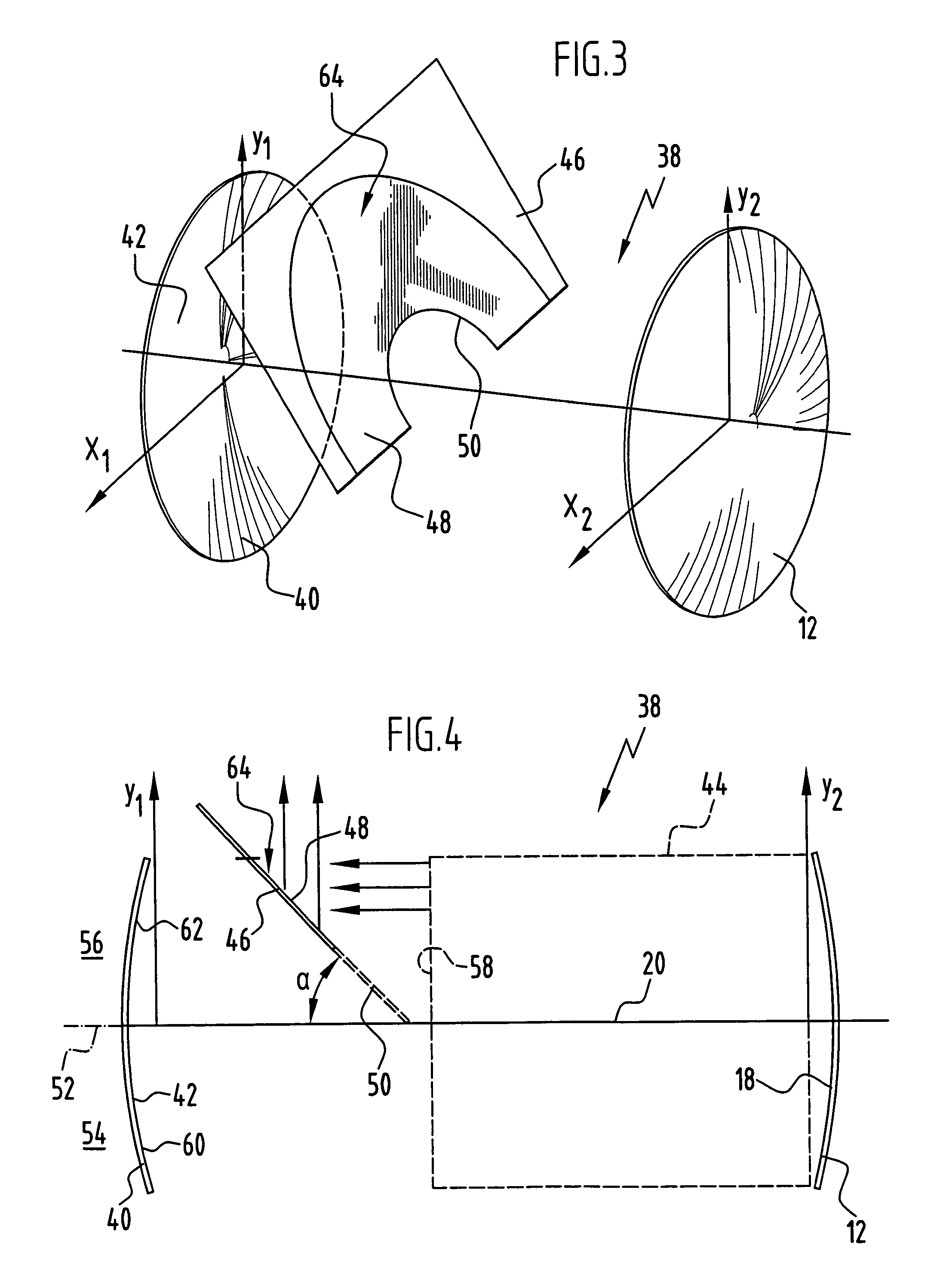
[0050]In an unstable confocal negative-branch resonator according to the invention, which is shown schematically in FIGS. 3 and 4 and generally designated therein by reference numeral 38, the back mirror is basically of the same design as described hereinabove. The same reference numerals are therefore used therefor. The back mirror 12 is again arranged symmetrically in relation to the optical axis 20. An outcoupling mirror 40 is provided. This again has a spherically concave surface 42 facing an optical medium 44 or a receptacle or flow space for an optical medium. The outcoupling mirror 40 is of symmetrical design with a radius (based on an imaginary sphere, the surface 42 of which represents a surface region) which is smaller than the radius of a corresponding imaginary sphere for the back mirror 12. The focal point of the two confocal mirrors 12 and 40 coincides (negative branch), and this focal point preferably lies closer to the outcoupling mirror 40.

[0051]For the asymmetrical...


PUM


Abstract

An unstable optical resonator for an optically active medium comprising a spherical back mirror and a spherical outcoupling mirror is proposed, and an outcoupling which is asymmetrical in relation to the optical axis takes place therein.

Description

CROSS-REFERENCE TO RELATED APPLICATION[0001]The present application claims the benefit of German Application No. 10 2004 008 640.0, filed Feb. 21, 2004, which is incorporated herein by reference in its entirety and for all purposes.FIELD OF THE INVENTION[0002]The invention relates to a resonator for an optically active medium. The invention further relates to a laser device and, in particular, a gas laser device with such a resonator.BACKGROUND OF THE INVENTION[0003]Optical resonators are known, for example, from the publication “Optische Resonatoren für Hochleistungs-Festkörper-Laser” (Optical Resonators for high-power solid-state Lasers) by N. Hodgson, Festkörper-Laser-Institut Berlin GmbH, internal report, December 1990 or from the article “Analysis of stable-unstable free electron laser resonators” by C.-C. Shih, SPIE Vol. 1868, pages 278 to 285. The article “Improvement of slab-laser beam divergence by using an off-axis unstable-stable resonator” by K. Kuba et al. (Optics Lette...

Claims


Application Information

Patent Timeline
Patent Type & Authority Patents(United States)
IPC IPC(8): H01S3/08H01S3/036H01S3/22
CPCH01S3/08081H01S3/036H01S3/22H01S3/08068
Inventor HALL, THOMAS
Owner DEUTSCHES ZENTRUM FUER LUFT & RAUMFAHRT EV
Learn More