Frequency converter assembly and method of using frequency converter assembly

a technology of frequency converters and components, applied in the direction of dynamo-electric converter control, motor/generator/converter stoppers, ac motor stoppers, etc., can solve the problem of increasing manufacturing costs and achieve the effect of reducing manufacturing costs

Active Publication Date: 2008-08-05
ABB (SCHWEIZ) AG
View PDF6 Cites 1 Cited by
  • Summary
  • Abstract
  • Description
  • Claims
  • Application Information

AI Technical Summary

Benefits of technology

[0008]The frequency converter assembly of the invention may be implemented with fewer components than a corresponding prior art assembly. Thus, the frequency chopper assembly of the invention may be constructed in a smaller space and the manufacturing costs thereof are lower.

Problems solved by technology

To provide a frequency converter with both terminals allowing the connection of an external brake resistor and poles allowing the supply of direct-voltage power out of and / or into the direct-voltage intermediate circuit is problematic, because the great number of terminals requires a lot of space and increases manufacturing costs.

Method used


Image

  • Frequency converter assembly and method of using frequency converter assembly
  • Frequency converter assembly and method of using frequency converter assembly

Examples


Embodiment Construction

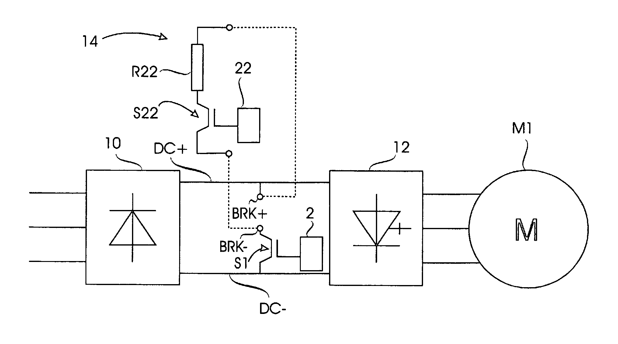
[0012]A frequency converter assembly of FIG. 1 comprises a direct-voltage circuit and brake chopper means. The direct-voltage circuit is electrically located between a rectifier unit 10 and an inverter unit 12. The alternating-voltage side of the rectifier unit 10 is connected to a supplying electrical network and its direct-voltage side is connected to the direct-voltage circuit of the frequency converter assembly. The direct-voltage side of the inverter unit 12 is connected to the direct-voltage circuit and its alternating-voltage side to a motor M1 to be supplied.

[0013]The direct-voltage circuit includes a first branch DC+, which has a positive voltage during operation, and a second branch DC−, which has a negative voltage during operation. The brake chopper means comprise a first terminal BRK+, a second terminal BRK−, a brake chopper switch S1, and programmable control means 2.

[0014]The brake chopper switch S1 is an IGBT transistor. The emitter of the brake chopper switch S1 is ...


PUM


Abstract

A frequency converter assembly comprising a direct-voltage circuit and brake chopper means, the direct-voltage circuit including a first branch (DC+) and a second branch (DC−), and the brake chopper means including a first terminal (BRK+), a second terminal (BRK−), a brake chopper switch (S1) and control means (2). The brake chopper switch (S1) is arranged in its closed position to provide a braking connection, in which the first branch (DC+) is electrically connected to the first terminal (BRK+) and the second branch (DC−) is electrically connected to the second terminal (BRK−). The assembly is provided with a first operating state where the control means (2) are arranged to control the brake chopper switch (S1) selectively to the closed position and the open position in response to the desired power supply direction of the direct-voltage circuit. The assembly is further provided with a second operating state where the control means (2) are arranged to maintain the brake chopper switch (S1) continuously in the closed position.

Description

BACKGROUND OF THE INVENTION[0001]The invention relates to frequency converters provided with a brake chopper switch.[0002]It is known to connect a brake chopper switch and a brake resistor to direct-voltage intermediate circuits of frequency converters in such a manner that, when the brake chopper switch is in its closed position, current flows from the positive branch of the direct-voltage intermediate circuit to the negative branch of the direct-voltage intermediate circuit via the brake resistor. Such a connection allows the braking of a motor supplied by the frequency converter. The brake resistor may be an internal or external component. An internal brake resistor may be a component integrated into the frequency converter, and an external brake resistor may be a detachably attachable component. The frequency converter may comprise a positive terminal and a negative terminal, between which the external brake resistor may be connected.[0003]It is also known to use the direct-volt...

Claims


Application Information

Patent Timeline
Patent Type & Authority Patents(United States)
IPC IPC(8): H02M5/40H02M5/44H02MH02P3/22H02P5/74
CPCH02P3/22H02P5/74H02M5/4585H02M1/32H02P27/06H02M5/458
Inventor VIROLAINEN, PANUSUOMELA, KALLE
Owner ABB (SCHWEIZ) AG
Why Eureka
Try Eureka