
Step-phase interferometric optical interleaver

a step-phase, optical interleaver technology, applied in the field of optical communication, can solve the problems of reducing the degree to which these interleavers can be utilized, limiting the degree to which they can be used, and reducing the usefulness of these interleavers, so as to reduce the contribution to phase error due to the reflectivity of the front surface of the cavity in conventional construction, and virtually eliminate the contribution of etalon structure to phase error

Inactive Publication Date: 2008-08-05
OPTOPLEX CORP
View PDF5 Cites 9 Cited by
  • Summary
  • Abstract
  • Description
  • Claims
  • Application Information

AI Technical Summary

Benefits of technology

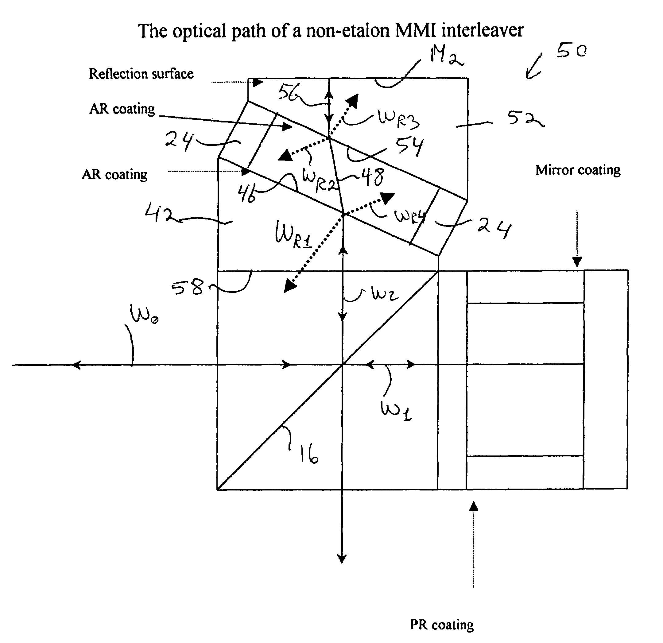
[0019]This invention is based on the idea of reducing the contribution to phase error in an interferometric interleaver by diverging from the optical path any reflection from the front surface of the mirror arm and by removing the etalon effect produced by the front surface and the parallel mirror. Thus, according to one aspect of the invention, the conventional cavity in the mirror arm of the interleaver is replaced by an optical wedge either in optical contact or integral with the beamsplitter structure of the interleaver. Thus, the light from the splitter is directed toward an AR-coated surface of the wedge at an interface with air. As a result of the angle introduced by the wedge, the light reflected from the splitter strikes the wedge's surface at a non-zero angle of incidence and, to the extent the surface exhibits any reflectivity, it produces a corresponding off-axis reflected beam that is dispersed away from the optics of the device. Therefore, the contribution to phase error due to the reflectivity of the front surface of the cavity in conventional construction is virtually eliminated.
[0020]The beam emerging from the wedge surface is refracted by the glass / air interface. According to another aspect of the invention, the mirror is tilted with respect to the wedge surface at such an angle that the beam emerging from the wedge is reflected totally on-axis by the mirror and returned to the point of emergence in the wedge surface, where it is again refracted at the air / glass interface and returned to the beamsplitter along the optical path of the mirror arm of the interleaver. As a result of the non-parallel disposition of the wedge surface and the mirror, the multiple-reflection contribution of the conventional etalon structure to the phase error is also virtually eliminated.
[0021]In another embodiment of the invention, the conventional cavity configuration of the mirror arm of the interleaver is retained, but the cavity is incorporated at an angle with respect to both the beamsplitter and the mirror. Building on the same optical wedge configuration of the first embodiment, a second optical wedge is used with an AR-coated surface that defines a cavity in combination with the first wedge's AR-coated surface, and with a reflective surface to provide the mirror of the interleaver. Spacers between the AR-coated surface of the first wedge and the AR-coated surface of the second wedge are used to set the optical-path length of the mirror arm to the required value. Thus, the light from the beamsplitter that is reflected at the front surface of the cavity is dispersed away from the optical path of the device, as in the case of the first embodiment. The light emitted from the front surface is refracted in air toward the AR-coated back surface of the cavity at a non-zero angle of incidence to ensure, to the extent that such surface also exhibits any reflectivity, that it produces an off-axis reflected beam that is also dispersed away from the optics of the device. The mirror surface of the second wedge is positioned at an angle with respect to the AR-coated back surface such that the emergent beam therefrom is nearly normal to and therefore reflected substantially on-axis by the mirror-and returned to the point of emergence in the AR-coated back surface, where it is sequentially refracted at the glass / air interface of the back surface and the air / glass interface of the AR-coated front surface, and then returned to the beamsplitter along the optical path of the mirror arm of the interleaver. Again, as a result of the lack of multiple reflections in the cavity formed between the two wedges of the invention, the etalon-structure contribution to phase error is virtually eliminated. Therefore, a broad benefit of this invention is a novel structural interleaver configuration that affords the precise control of the phase shift required for maximizing channel isolation.

Problems solved by technology

Currently, the standard channel spacing is 100 GHz (0.8 nm) and manufacturing costs increase dramatically to implement a channel spacing smaller than 100 GHz.
Several complicating factors limit the degree to which these interferometric interleavers can be utilized to increase communication capacity.
For instance, the non-linear dependence of the optical phase on carrier frequency of the interleaver intrinsically introduces undesirable chromatic dispersion that reduces their usefulness.
Another problem arises from the way interleavers are in fact manufactured in order to simplify the challenge of controlling precisely the optical-path length of each arm of the device.
In practice, a reflectivity of less than 10 percent is tolerated because of limits in the effectiveness of antireflective coatings, but a corresponding phase error is introduced that severely limits the use of interleavers to improve the capacity of optical communication systems.
As those skilled in the art would readily recognize, in the pass band of optical frequency processed by an interferometric interleaver, the two beams are in phase, causing constructive interference.
In the stop band of the optical frequency, the two beams are out of phase and, therefore, interfere destructively.
However, any variation from 180-degree in the phase difference between the two interfering beams (herein defined as “phase error”) significantly degrades the performance of the interleaver.
Accordingly, the graph of FIG. 3 shows that a maximum phase error of 5 degrees is acceptable, which is very difficult to achieve with traditional interleaver construction.
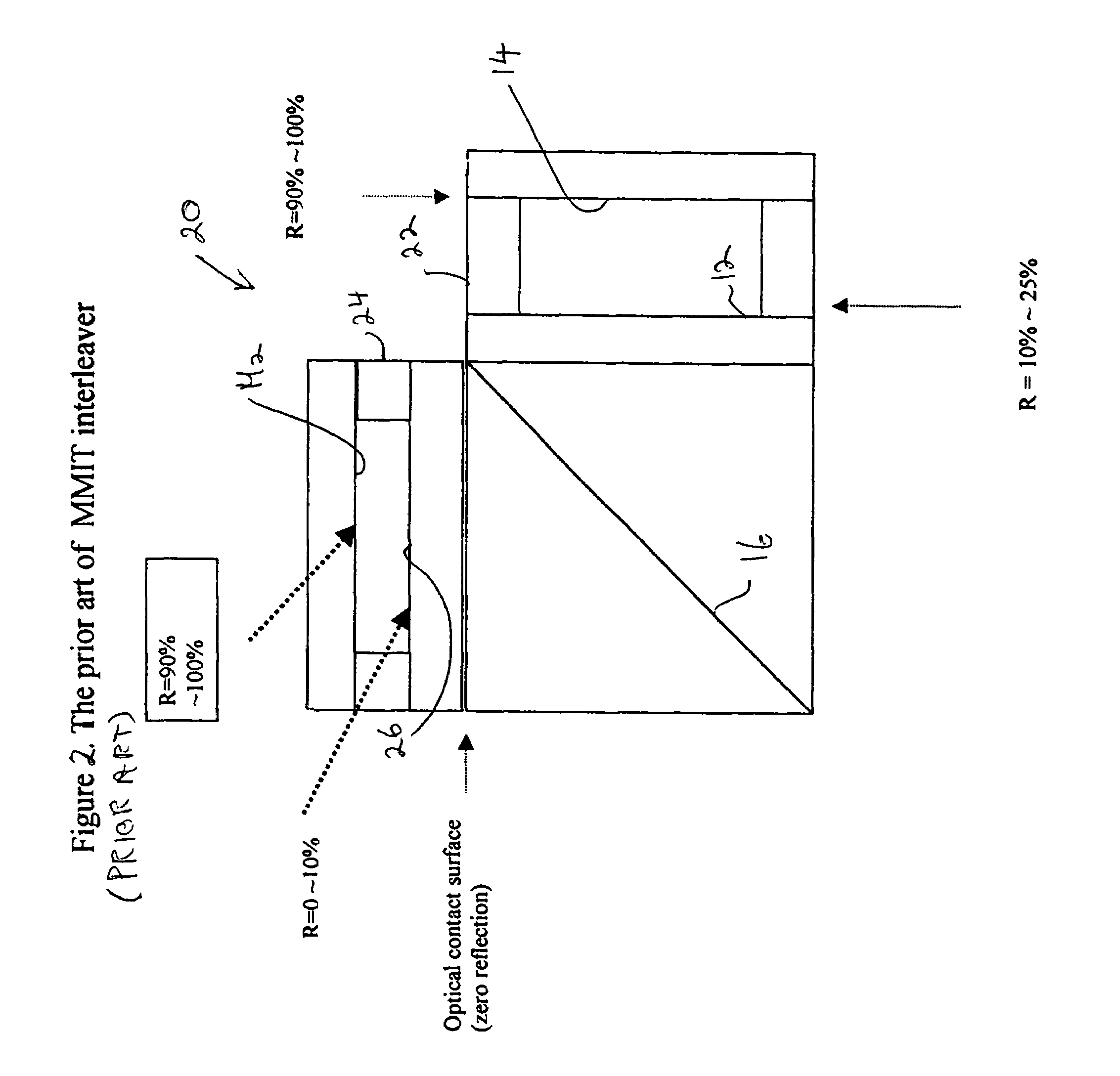
For an interleaver of the type shown in FIG. 1 (see also B. Dingel et al., “Multifunction optical filter with a Michelson-Gires-Tournois interferometer for wavelength-division-multiplexed network system applications,” Optics Letters, Vol. 23, No. 14, 1998), the phase difference between the beams reflected by the GTR and the Mirror M2 is nearly 180 degrees in the stop band and, therefore, the two beams interfere destructively.
The phase difference in the pass band is nearly in phase; thus, they interfere constructively.
It is noted that a reflectivity of 0.25% produces a phase error of about 6 degrees, which degrades channel-isolation performance to an unacceptable degree.
This is almost impossible to implement with existing AR coatings.
To the extent that the resonator cavity Mc (see FIG. 1) is necessary to the function of an interferometric interleaver, the corresponding phase error is unavoidable.
Unfortunately, antireflective (AR) coatings are not sufficiently effective to control the reflectivity of a surface to the degree necessary to precisely control phase error.

Method used


Image

  • Step-phase interferometric optical interleaver
  • Step-phase interferometric optical interleaver
  • Step-phase interferometric optical interleaver

Examples


Embodiment Construction

[0036]The invention lies in providing an novel interleaver structure that virtually eliminates the phase errors introduces by the prior-art configuration of the mirror arm of the interleaver. Referring to FIG. 7 of the drawings, wherein like parts are designated throughout with like numerals and symbols, a non-etalon mirror-arm interleaver 40 is illustrated according to the invention. The GTR arm of the interleaver (that is, the parallel surfaces 12,14 and the cavity between them) is unchanged from conventional construction. In the mirror arm, on the other hand, the cavity defined by the surface 26 and the mirror M2 (FIG. 2) is eliminated and replaced by an optical wedge 42 in optical contact with the beamsplitter structure 44, so as to achieve a condition of zero reflection between the two. Equivalently, the wedge42 may be constructed as an integral part of the beamsplitter structure. The surface 46 of the wedge 42 is treated with an AR coating, as in conventional devices, in order...


PUM


Abstract

The cavity in the mirror arm of a conventional interleaver is replaced by a wedge integral with the beamsplitter structure of the interleaver. Thus, the light reflected from the AR-coated surface of the wedge is dispersed away from the optics of the device. The beam emerging from the wedge surface is directed toward a tilted mirror that reflects it totally on-axis. As a result of the diversion of the light reflected from the wedge surface and the non-parallel disposition of the wedge surface with respect to the mirror, phase errors are virtually eliminated. In another embodiment, a second wedge is used with a second antireflective surface disposed in parallel to the first wedge's antireflective surface, and with a mirror normal to the optical axis of the device.

Description

RELATED APPLICATIONS[0001]This application is based on U.S. provisional Ser. No. 60 / 346,708, filed Jan. 8, 2002.BACKGROUND OF THE INVENTION[0002]1. Field of the Invention[0003]This invention pertains to the general field of optical communications and, in particular, to a step-phase interferometric optical interleaver.[0004]2. Description of the Prior Art[0005]Interferometric optical interleavers are commonly utilized in dense wavelength division multiplexing (DWDM) optical communication, where various frequencies (1 / λ) of laser light are used as carrier signals (channels) and are coupled into the same optical fiber, which acts as a waveguide. Data signals are superimposed over the carrier signals and are transported in the waveguide. Thus, the information capacity is directly proportional to the number of channels in the fiber. Since the total usable wavelength range is limited (about a few tens of nanometers), as channel spacing decreases, more channels can fit into the same optica...

Claims


Application Information

Patent Timeline
Patent Type & Authority Patents(United States)
IPC IPC(8): G02B27/00G01B9/02
CPCH04J14/02G02B6/2813G02B6/29358G02B6/29344
Inventor HSIEH, YUNG-CHIEHAI, CHIAYU
Owner OPTOPLEX CORP
Learn More